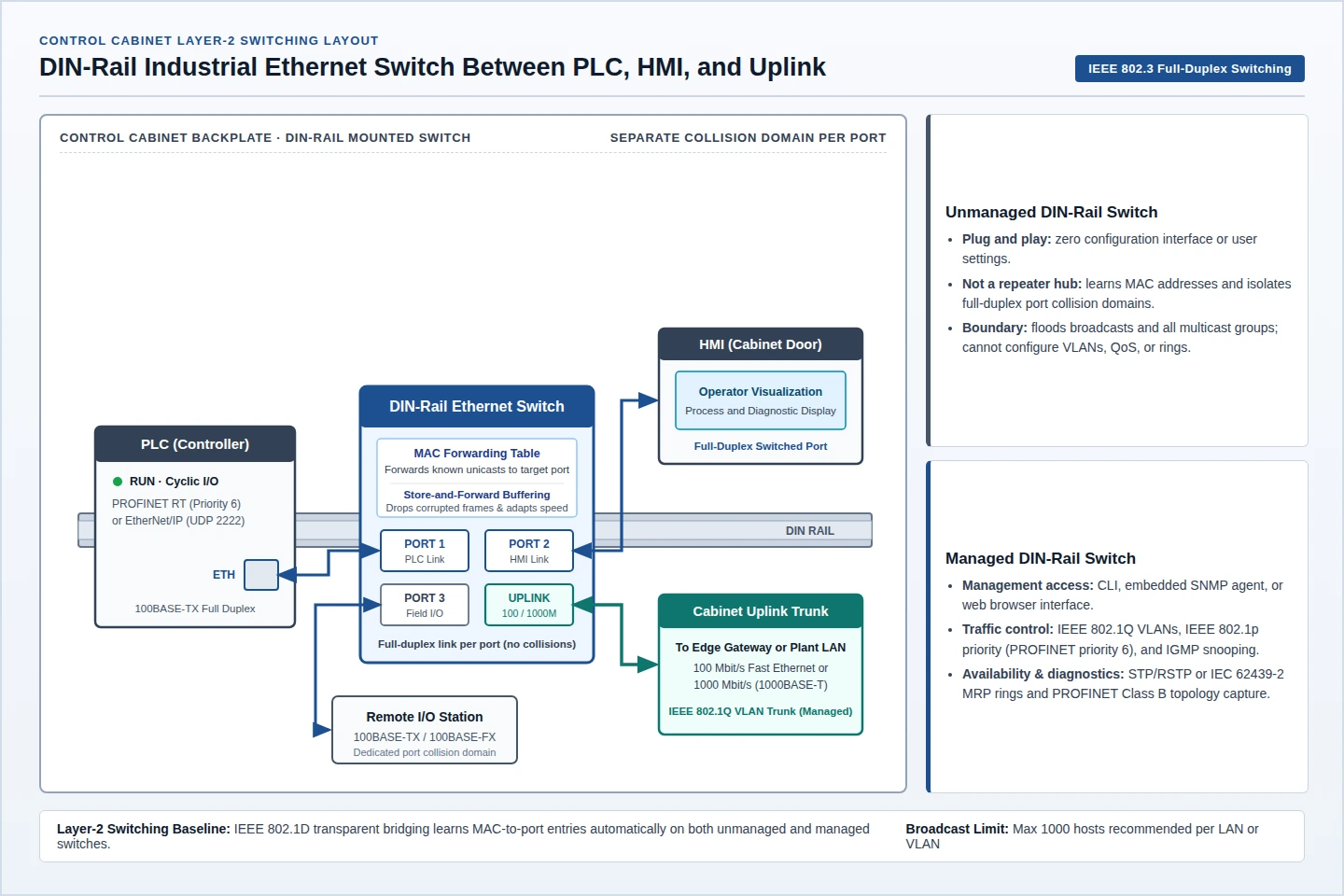
A managed industrial Ethernet switch provides one or more management interfaces—such as a command-line interface, an embedded SNMP agent, or a web browser interface—to configure virtual LANs (VLANs), quality-of-service priority queues, IP multicast filtering, and ring recovery, whereas an unmanaged network switch has no configuration interface or user options. Even as a plug-and-play device, an unmanaged switch still learns connected MAC addresses in a forwarding table and sends known unicast frames only to the addressed port across full-duplex links rather than repeating every signal out all ports like a half-duplex Ethernet hub.
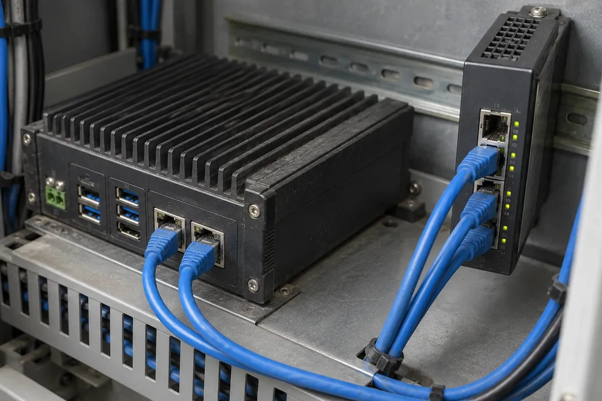
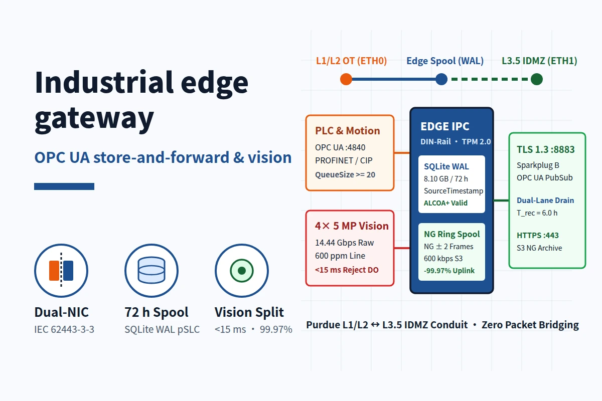
Industrial Ethernet is Ethernet in an industrial environment with deterministic real-time protocols including PROFINET and EtherNet/IP, and the name can also mean standard Ethernet with DIN-rail switches, rugged connectors, and extended-temperature hardware for temperature extremes, humidity, and vibration that exceed controlled IT rooms. Within the three-layer model in A plain map of device, gateway and platform, cabinet switches connect controllers, HMIs, and field I/O at the device layer, while zone-boundary protocol termination, local outage spooling, and camera offload belong to an industrial edge gateway documented in the Industrial Connectivity section.
| Switch Tier | Management Access | Layer-2 Forwarding Baseline | Configurable Traffic & Topology Controls | Plant Cell Fit |
|---|---|---|---|---|
| Unmanaged switch | None; plug-and-play operation with zero user settings | Learns MAC addresses per port; creates separate full-duplex collision domains; floods broadcasts and default multicasts | No VLAN assignment, QoS setup, multicast snooping, or loop-blocking configuration | Isolated star of machine ports with a single uplink and no ring, VLAN, or IP multicast pruning requirement |
| Web-managed switch | Web browser interface; usually no command-line interface | Full-duplex Layer-2 MAC table learning and buffered port speed adaptation | Basic settings including VLANs, port bandwidth, and duplex | Small segmented cells needing basic VLAN or port-rate settings without full SNMP or CLI automation |
| Managed switch | One or more of a command-line interface, an embedded SNMP agent, or a web browser interface | Full-duplex Layer-2 MAC table learning and buffered port speed adaptation | Quality of service and monitoring, IEEE 802.1Q VLAN tagging, IGMP snooping, Spanning Tree, and IEC 62439-2 MRP rings | Production lines needing PROFINET Conformance Class B diagnostics, EtherNet/IP multicast pruning, VLAN trunks, or ring recovery |
Unmanaged Switch vs Ethernet Hub and Store-and-Forward vs Cut-Through
Understanding what an unmanaged switch already performs in hardware prevents confusing a non-configurable switch with a deprecated repeater hub. Operating at the physical layer without memory to store frames, a repeater hub reproduces an incoming signal on every port except the arrival port, handles only one transmission at a time, and runs solely in half-duplex mode. As of 2011, IEEE 802.3 deprecated connecting network segments with repeaters or hubs.
An Ethernet switch operates at OSI Layer 2 to create an independent collision domain on every port, and on a full-duplex link with one transmitter and one receiver per collision domain, collisions are impossible. As explained in Loyola University Chicago’s Ethernet chapter, switches build their forwarding tables through IEEE 802.1D transparent bridging: the bridge records each source MAC address in a table held in high-speed memory, maps that address to its port, and on some switch brands calls that table a CAM table. When a destination MAC address is not yet in the forwarding table, the switch falls back to unknown-unicast flooding out every interface except the arrival port until a frame from that MAC address arrives, while broadcast frames continue to reach every port in the broadcast domain.
Cabinet switches also differ in how they buffer and verify frames between ports:
- Store-and-forward switching: Bridges buffer incoming packets, adapt transmission speed between differing incoming and outgoing port rates, and drop corrupted frames before transmission.
- Cut-through switching: The switch begins forwarding a frame as soon as the destination address and outgoing interface are identified, before the entire frame arrives. Compared with store-and-forward switching, cut-through lowers switch latency, relies on destination devices for error handling, and forwards corrupted frames onto the wire.
When Do VLANs, PROFINET Priority, and EtherNet/IP Multicast Require a Managed Switch?
An unmanaged switch suffices when a machine cell is a standalone star of full-duplex links with no shared trunk, no ring loop, and no heavy IP multicast streams. Moving to a managed switch—or to a web-managed switch for basic browser-configured VLAN, port-bandwidth, and duplex settings—becomes necessary as soon as the cell requires IEEE 802.1Q segmentation, priority queuing, SNMP topology diagnostics, or IGMP snooping.
IEEE 802.1Q VLAN Tagging and Priority Code Point Fields
IEEE 802.1Q defines VLAN tagging on IEEE 802.3 Ethernet networks together with the quality-of-service prioritization scheme known as IEEE 802.1p. Inserting a 32-bit 802.1Q tag between the source MAC address and the EtherType field extends the maximum Ethernet frame size from 1,518 bytes to 1,522 bytes. Two bytes carry the tag protocol identifier (TPID) and two bytes carry tag control information (TCI), split into three fields:
- Priority Code Point (PCP): A 3-bit field referencing IEEE 802.1p class of service to map frames into distinct priority levels.
- Drop Eligible Indicator (DEI): The TCI field beside PCP and VID, which may be used alone or with PCP to indicate frames eligible to be dropped in the presence of congestion.
- VLAN Identifier (VID): A 12-bit field where values 0 and 4095 are reserved, supporting up to 4,094 usable VLANs. Value 0 designates a priority tag carrying IEEE 802.1p priority with no VLAN ID.
PROFINET Conformance Class B vs EtherNet/IP Implicit Multicast
PROFINET and EtherNet/IP place different demands on switch configuration because their cyclic I/O frames travel at different protocol layers:
| Protocol Dimension | PROFINET Real-Time & Diagnostics | EtherNet/IP Implicit & Explicit Messaging |
|---|---|---|
| Cyclic I/O transport | PROFINET Real-Time (RT) cyclic data and alarms travel directly over Ethernet; UDP/IP carries acyclic data | Basic I/O transfers via UDP-based implicit messaging on UDP port 2222; explicit messaging uses TCP port 44818 |
| Priority and cycle classes | IEEE 802.1Q priority tagging gives all real-time data priority 6 for minimum switch delay; RT Class A/B cycles run 1 to 10 ms and IRT Class C runs below 1 ms | Supports unicast, IP multicast, and broadcast over IP; unmanaged switches flood IP multicast across every port |
| Multicast filtering behavior | Direct Ethernet cyclic RT frames are prioritized via 802.1Q PCP priority 6 rather than IP IGMP group joins | IGMP snooping listens to IGMP traffic to map and prune IP multicast streams from ports that did not join |
| Managed infrastructure drivers | Conformance Class B stipulates certified infrastructure, SNMP device support, media/system redundancy, and managed switches for diagnostics and topology capture | IGMP snooping is a managed-switch feature, and the group tables can stay incomplete unless a querier is present, which some switches include |
Because switches have no built-in way to know where multicast subscribers sit, they flood multicast frames out all ports in a broadcast domain or VLAN by default, placing unnecessary processing load on non-subscribing controllers and drives. IGMP snooping inspects IGMP conversations between hosts and routers so switches forward IP multicast groups only to links that joined them. Engineers configuring IGMP snooping on an isolated EtherNet/IP cell face two operational limits:
- Requirement for an IGMP querier: Without a querier on the subnet, IGMP membership reporting and port-to-group tables can remain incomplete, preventing reliable snooping unless the managed switch includes an embedded IGMP querier capability.
- Equipment implementation differences: IGMP snooping is described in an informational IETF RFC while affecting IEEE bridging operations, so lacking a single authoritative standard, snooping behavior may differ across switch equipment.
How Do Managed Rings Prevent Switching Loops Compared with Unmanaged Stars?
Wiring a backup cable between switches to survive a cut cord creates a physical loop. Without a loop-control protocol blocking the redundant path, any frame whose destination is missing from the forwarding tables circulates endlessly around the switch loop, causing broadcast radiation and MAC table instability.
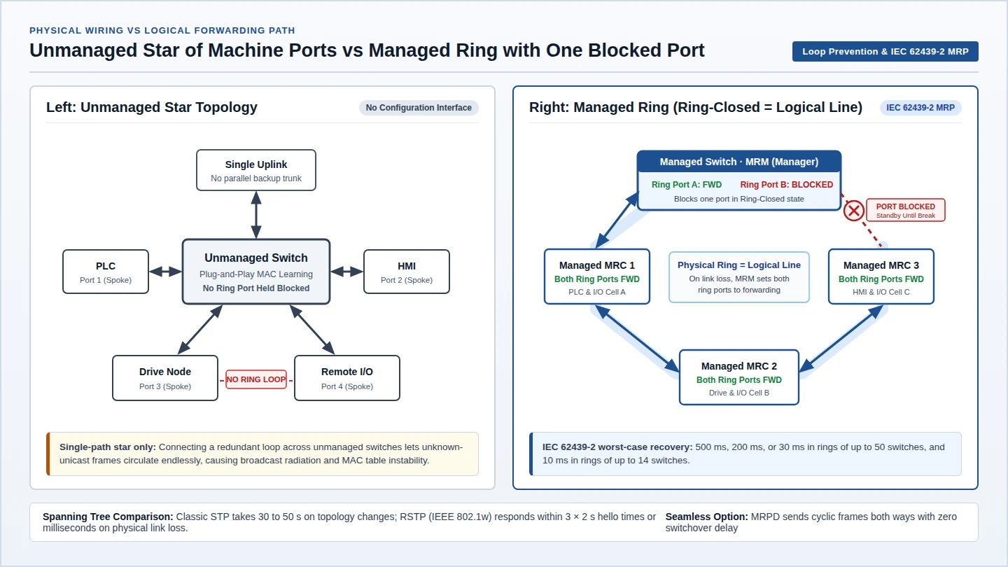
Managed industrial switches prevent bridge loops while preserving fault-tolerant backup links through either IEEE spanning-tree protocols or industrial ring protocols:
- Spanning Tree Protocol (STP) and Rapid Spanning Tree Protocol (RSTP): Classic STP builds a loop-free logical tree, holding a newly connected host port for roughly 30 seconds across listening and learning states (using a 15-second default forward delay set by the root bridge) and taking 30 to 50 seconds to respond to a topology change. Introduced in 2001 as IEEE 802.1w, backwards-compatible RSTP typically responds within 3 hello intervals—where the configurable hello time defaults to 2 seconds—or within a few milliseconds of a physical link failure. Functionality from STP (IEEE 802.1D), RSTP (IEEE 802.1w), and Multiple Spanning Tree Protocol (IEEE 802.1s) is consolidated in IEEE 802.1Q-2014.
- Media Redundancy Protocol (MRP, IEC 62439-2): Standardized by the IEC as IEC 62439-2, MRP enables rings of Ethernet switches to overcome any single failure with a recovery time much faster than Spanning Tree Protocol. During normal Ring-Closed operation, one ring port on the Media Redundancy Manager (MRM) stays blocked while its second ring port forwards, and both ring ports on every Media Redundancy Client (MRC) forward, reducing the physical ring to a loop-free logical line. When a link between two MRCs fails (Ring-Open), the MRM sets both ring ports to forwarding while the MRCs adjacent to the break have one disabled port and one forwarding port, restoring a logical line.
Recovery timing depends on the redundancy mechanism and standard scope:
- IEC 62439-2 worst-case guarantees: With the parameter sets specified in IEC 62439-2, MRP guarantees worst-case recovery times of 500 ms, 200 ms, or 30 ms in rings of up to 50 switches, and a worst-case recovery time of 10 ms in rings of up to 14 switches.
- PROFINET MRP switching context: In PROFINET ring deployments, MRP creates a protocol-independent ring topology with a switching time of less than 50 ms, which is often sufficient for standard real-time communication with PROFINET.
- Media Redundancy for Planned Duplication (MRPD): For error switchover without time delay, MRPD transmits cyclic real-time data in both directions around the ring topology, using a packet timestamp so the receiver removes redundant duplicates.
| Topology / Protocol | Standard Home | Loop Prevention Method | Documented Recovery / Convergence Behavior |
|---|---|---|---|
| Unblocked switch loop | None (active Layer-2 loop) | None; all switch ports forward | Fails with endless unknown-unicast circulation, broadcast radiation, and MAC table instability |
| Classic STP | Incorporated into IEEE 802.1Q-2014 (from 802.1D) | Blocks redundant links into a loop-free tree | About 30 s host-port startup (15 s default forward delay); 30 to 50 s topology-change response |
| Rapid Spanning Tree (RSTP) | Incorporated into IEEE 802.1Q-2014 (from 802.1w) | Active bridge port roles compatible with classic STP | Typically within 3 hello times (2 s default hello) or a few milliseconds on physical link loss |
| Media Redundancy Protocol (MRP) | IEC 62439-2 | MRM blocks one ring port in Ring-Closed state to form a logical line | IEC 62439-2 worst case: 500 ms, 200 ms, or 30 ms (up to 50 switches) and 10 ms (up to 14 switches) |
| Planned Duplication (MRPD) | PROFINET seamless media redundancy | Sends cyclic real-time frames in both ring directions | Zero switchover time delay; receiver drops duplicate frames via packet timestamp |
Fast Ethernet 100 Mbit/s vs Gigabit 1000 Mbit/s and Broadcast Domain Sizing
Port speed selection on a cabinet switch separates field-device attachment links from higher-speed aggregation trunks. Fast Ethernet physical layers carry traffic at a nominal 100 Mbit/s rate—succeeding the prior 10 Mbit/s Ethernet speed—with copper 100BASE-TX by far the most common physical layer. Gigabit Ethernet raises nominal link speed to 1000 Mbit/s, with copper 1000BASE-T defined by IEEE 802.3ab as its most popular variant.
For PROFINET field devices under Conformance Class A and Class B, standard 100BASE-TX electrical or 100BASE-FX optical full-duplex connections at 100 Mbit/s under IEEE 802.3 satisfy the hardware interface requirement, with mandatory autocrossover eliminating crossover cables. To wire field stations in a daisy-chained line rather than cabling every station back to a central cabinet switch, PROFINET recommends a 2-port switch integrated inside the field device. Where multiple 100 Mbit/s machine links aggregate onto a 1000 Mbit/s 1000BASE-T uplink, buffered switching adapts packet transmission speed between the two port rates.
When sizing port counts and subnet boundaries across interconnected switches, count attached controllers, drives, HMIs, sensors, and uplinks while keeping broadcast traffic bounded: because switched Ethernet forwards broadcasts to every port in a segment, a common recommendation is to keep each LAN or VLAN to no more than 1000 hosts.
What Are the Limits of Power over Ethernet in a Control Cabinet?
In field installations, Power over Ethernet (PoE) carries data and DC power over one twisted-pair Ethernet cable to networked powered devices (PDs) such as wireless access points, IP cameras, and VoIP phones. Specifying a PoE DIN-rail switch requires sizing both the per-port output at the power sourcing equipment (PSE) and the lower wattage that arrives at the field device after cable resistance losses.
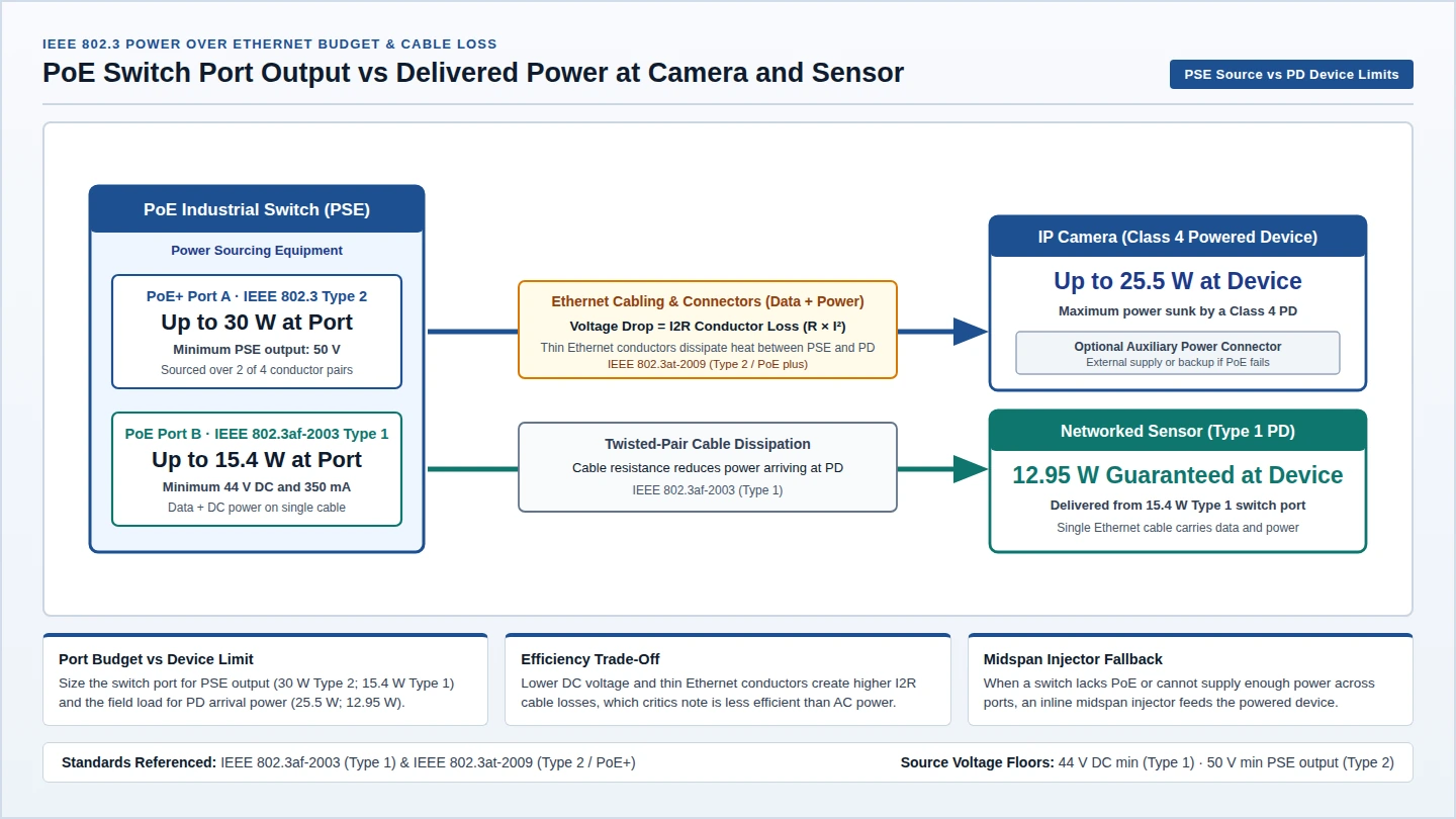
Two IEEE 802.3 PoE power tiers illustrate the gap between switch-port sourcing and powered-device delivery:
- Type 1 (IEEE 802.3af-2003): Supplies up to 15.4 W of DC power per switch port at a minimum of 44 V DC and 350 mA, with only 12.95 W guaranteed at the powered device because power dissipates in the cable.
- Type 2 (IEEE 802.3at-2009 / PoE plus): Introduces up to 25.5 W at the powered device. As detailed in the U.S. Department of Energy Power over Ethernet cable report, IEEE 802.3 permits a Class 4 powered device to sink up to 25.5 W from a Type 2 PSE port capable of sourcing up to 30 W over two of the four conductor pairs, with a minimum PSE output voltage of 50 V.
Four physical and operational constraints govern PoE deployment in industrial cabinets:
- Cable and connector I2R losses: Voltage drop in low-voltage Ethernet cables and connectors is an I2R loss, where power dissipated by an imperfect conductor equals its resistance multiplied by the square of the current it carries.
- Lower conversion efficiency than AC power: Critics note that PoE is inherently less efficient than AC power because of its lower voltage, and thin Ethernet conductors compound that loss.
- Midspan injector fallback when switch power is insufficient: When an existing cabinet switch lacks PoE or cannot supply enough power across active ports, an inline midspan injector installed between the switch and the powered device supplies the Ethernet power budget.
- Device auxiliary power connectors: Many powered devices include an auxiliary power connector for an external supply that can deliver part or all of the device load and provide backup power if PoE fails.