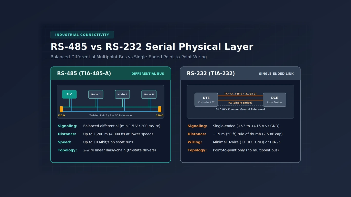
RS-485 uses balanced differential twisted-pair signaling with three-state drivers to support multipoint linear buses up to 10 Mbit/s or distances up to 1,200 m (4,000 ft) at lower speeds, whereas RS-232 uses single-ended, ground-referenced signaling over short point-to-point links capped by a 2.5 nF load capacitance limit—roughly 15 m (50 ft) as a common rule of thumb.
Within the three-layer model outlined in A plain map of device, gateway and platform, serial physical layers connect field meters, drives, and legacy controllers at the device layer before an industrial edge gateway bridges plant telemetry upstream. Both standards sit in the Industrial Connectivity physical layer, yet their electrical design determines whether a link works only inside one cabinet or reliably across a factory floor.
| Specification | RS-232 (Recommended Standard 232) | RS-485 (TIA-485-A / EIA-485) |
|---|---|---|
| Year introduced | 1960 (ANSI/EIA-232-D revised 1986) | 1983 |
| Electrical signaling | Single-ended, referenced to common signal ground (0 V) | Balanced differential across twisted-pair A and B lines |
| Signal voltage levels | +3 to +15 V or -3 to -15 V (25 V max open-circuit) | Minimum 1.5 V differential across 54-ohm load; 200 mV receiver threshold |
| Maximum distance | Not fixed by standard; 2.5 nF capacitance limit (~15 m / 50 ft rule of thumb) | Up to 1,200 m (4,000 ft) at lower data rates |
| Maximum data rate | Lower speed; constrained by large voltage swings and capacitance | Up to 10 Mbit/s on shorter cable runs |
| Topology and drops | Point-to-point between DTE and DCE; no multipoint capability | Linear multipoint daisy-chain bus (two-wire half-duplex or four-wire full-duplex) |
| Connector specification | DB-25 incorporated in ANSI/EIA-232-D (minimal 3-wire links common) | No connector or pinout mandated (screw terminals, D-subminiature, or other) |
What Are the Key Differences Between RS232 and RS485 Communication Interfaces?
RS-232 (Recommended Standard 232), introduced in 1960 for serial data transmission between DTE and DCE, delivers lower speed, shorter cable reach, larger voltage swings, larger connectors, and no multipoint capability compared with RS-485. Introduced in 1983 as TIA-485(-A) or EIA-485, RS-485 replaces ground-referenced signaling with balanced differential twisted-pair signaling and three-state drivers for inexpensive local networks and multidrop industrial buses.
Voltage Swings, Capacitance Limits, and Single-Ended Ground Sensitivity
RS-232 relies on large positive and negative voltage swings referenced to a shared signal ground. That electrical architecture increases power consumption, complicates power supply design, and caps the upper operating speed of compatible transceivers. Rather than publishing a fixed cable-length ceiling, ANSI/EIA-232-D (published in 1986 alongside formal DB-25 connector standardization) sets a 2.5 nF circuit capacitance limit that compliant drivers must tolerate. In field installations, a widely used rule of thumb treats cables longer than 15 m (50 ft) as having excessive capacitance unless low-capacitance cable is specified.
Differential Twisted-Pair Signaling and Receiver Threshold Margin
RS-485 transmits binary states as the voltage polarity between two twisted conductors rather than measuring a single wire against earth or chassis ground. Using balanced differential signaling over twisted pair allows RS-485 networks to reach data rates up to 10 Mbit/s or, at lower speeds, span distances up to 1,200 m (4,000 ft). Because each driver uses three-state logic that can be deactivated when not transmitting, multiple stations share the same two-wire linear bus without bus contention.
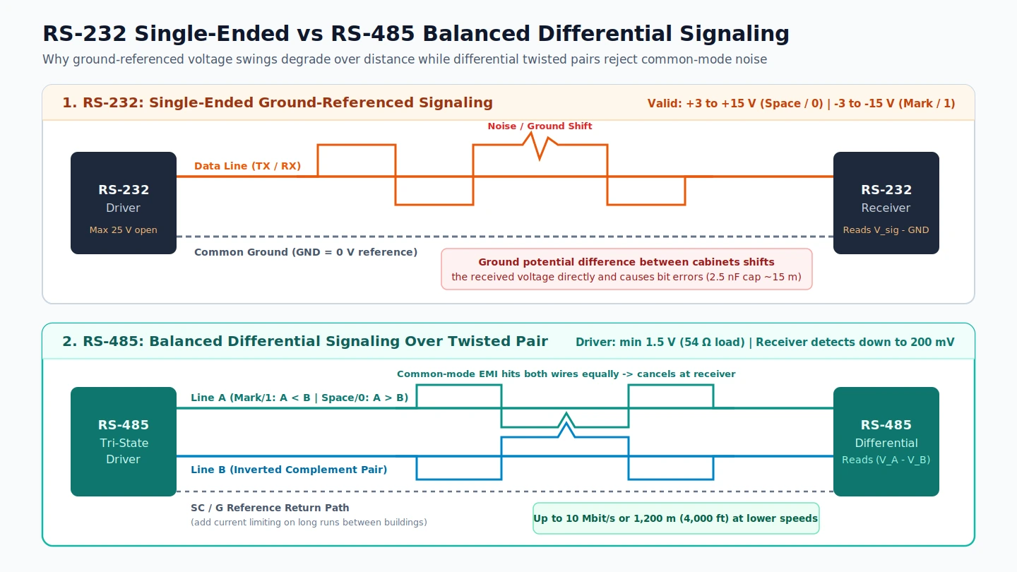
How Do RS485 vs RS232 Voltage Levels Handle Common-Mode Noise and Grounding?
RS-232 receivers depend on the common ground pin remaining at 0 V at both ends of the cable, so ground potential differences between connected machinery and computers directly degrade signal integrity. RS-485 drivers output at least 1.5 V differentially across a 54-ohm load while receivers detect differential inputs down to 200 mV, rejecting noise that couples equally onto both twisted wires while still requiring a controlled reference return path.
On RS-232 data lines, valid signals sit in the range of +3 to +15 V or -3 to -15 V relative to the common ground pin, leaving voltages between -3 V and +3 V invalid. The standard permits a maximum open-circuit voltage of 25 V, and signal levels of +/-5 V, +/-10 V, +/-12 V, and +/-15 V are commonly seen depending on driver supply rails. Because single-ended signaling references every bit to the shared ground wire, noise immunity and transmission distance remain limited whenever two cabinets sit at different ground potentials.
RS-485 defines logic states strictly by polarity between the A and B terminals:
- Off, mark, or logic 1 state: The driver’s A terminal is negative relative to the B terminal.
- On, space, or logic 0 state: The driver’s A terminal is positive relative to the B terminal.
Even though differential signaling rejects common-mode interference across A and B, TIA-485 still requires a third common return path—labeled SC, G, or reference—connecting circuit grounds along the balanced line for proper operation. Over long cable runs, grounds between buildings may vary by a small voltage; adding current limiting to the SC connection prevents disparate ground potentials from driving damaging return currents through the reference wire.
How Does RS485 vs RS232 Wiring Differ Between Point-to-Point and Daisy-Chain Buses?
RS-232 connects two devices point-to-point—commonly using a minimal 3-wire link carrying transmit data, receive data, and signal ground when hardware handshaking is unnecessary—and provides no multipoint bus support. RS-485 activates three-state drivers so multiple stations connect along a two-wire half-duplex linear daisy-chain bus (or four wires for full-duplex), terminating on screw terminals, D-subminiature connectors, or other connectors because RS-485 mandates no fixed pinout.
In a control cabinet, RS-232 wiring remains straightforward when connecting a single diagnostic laptop or local barcode reader to one controller port over a short cord. Attempting to branch multiple field instruments onto one RS-232 port fails because the standard has no multipoint capability and only limited multidrop capability.
On a factory floor, RS-485 wiring chains nodes linearly from one terminal block to the next:
- Two-wire half-duplex linear bus: Uses one twisted differential pair (plus the SC reference return) with tri-state transceivers taking turns transmitting on the shared bus.
- Four-wire full-duplex bus: Adds a second differential pair so RS-485 operates full-duplex like RS-422, though this is not necessary or desirable in many multipoint cases.
- No mandated connector: Field devices land RS-485 conductors on screw terminals, D-subminiature plugs, or custom industrial headers, requiring technicians to verify A/B polarity labels at every drop.
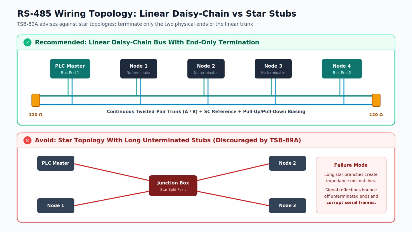
Why Is a 120-Ohm Termination Resistor Used at Both Ends of an RS485 Bus?
Ideally, both physical ends of an RS-485 cable carry a termination resistor across the differential pair matched to the cable characteristic impedance—typically 120 ohms for twisted pairs—to absorb traveling waves and prevent signal reflections off unterminated ends from corrupting data. Termination resistors also reduce electrical noise sensitivity by lowering line impedance, while pull-up and pull-down biasing resistors hold idle lines at known voltages.
Two physical-layer failure modes account for most intermittent CRC errors on industrial RS-485 trunks:
- Missing end termination and floating idle lines: Without termination resistors at the two cable ends, signal edges reflect back down the trunk and corrupt incoming frames. Furthermore, when all device stations are silent or unpowered, undriven data lines float at peak electrical noise sensitivity unless pull-up and pull-down biasing resistors establish a known idle bias voltage so receivers do not interpret noise as data.
- Star topology with long stubs: TSB-89A (Application Guidelines for TIA/EIA-485-A) explicitly does not recommend star topology. Splitting a serial trunk from a central junction box creates long stubs—the branches of the star—that generate signal reflections and make data transmission unreliable. Keeping drops linear along one trunk and placing termination resistors strictly at the two physical ends preserves signal integrity.
Can a Cat6 Cable Be Used for RS485 Field Wiring?
Category 6 cable (Cat 6) is a standardized pure-copper twisted-pair cable specified up to 250 MHz with stricter crosstalk and system noise limits than Cat 5 or Cat 5e (100 MHz). Because RS-485 requires differential signaling over twisted pair without mandating a specific connector, pure-copper twisted-pair cabling can carry the A/B pair and SC reference path, provided copper-clad aluminium (CCA) wire is avoided and shielding with a continuous drain wire is used in high-EMI areas.
When evaluating structured Ethernet cabling for an RS-485 serial run in an industrial plant, check three physical requirements:
- Verify pure copper conductors: The Cat 6 specification mandates pure copper conductors, yet counterfeit or non-compliant copper-clad aluminium (CCA) cable is common in the market and should be rejected for industrial field wiring.
- Maintain twisted-pair pairing and SC reference: Assign one intact twisted pair to the balanced A and B lines and use an additional conductor for the SC common reference path (with current limiting across long inter-building runs).
- Add shielding in high-EMI environments: In electrically noisy areas near drives or motors, cable shielding may be required to avoid data corruption, with shielding continuity maintained from one cable end to the other via a drain wire.
Where Does RS422 Fit When Comparing RS485 vs RS232 vs RS422?
RS-422 bridges RS-232 and RS-485 by pairing every data line with a dedicated differential return line—supporting up to 10 Mbit/s at 12 m (40 ft) with speed decreasing over longer cable runs—typically wired over two shielded twisted pairs plus a ground wire. However, because an RS-422 driver cannot be switched off, it supports only one driver fanning out to up to ten receivers rather than a true multipoint bus.
| Interface Feature | RS-232 | RS-422 | RS-485 |
|---|---|---|---|
| Signaling method | Single-ended vs common ground | Differential (dedicated return per data line) | Balanced differential over twisted pair |
| Driver control | Always-on point-to-point driver | Always-on driver (cannot be switched off) | Three-state driver (can be deactivated) |
| Node topology | 1 driver to 1 receiver (no multipoint) | 1 driver fanning out to up to 10 receivers | True multipoint linear bus (multiple transceivers) |
| Typical cable wiring | Minimal 3-wire (TX, RX, GND) or DB-25 | 2 twisted pairs (often shielded) + ground wire | Twisted pair (2-wire) or 2 pairs (4-wire) + SC |
| Documented speed / reach | ~15 m (50 ft) rule of thumb (2.5 nF cap) | Up to 10 Mbit/s at 12 m (40 ft); drops with length | Up to 10 Mbit/s or up to 1,200 m (4,000 ft) at lower speeds |
RS-485 and RS-422 can interoperate under certain restrictions, and RS-485 can be wired in four-wire full-duplex mode similar to RS-422. Still, whenever multiple field controllers or sensors share a cable for bidirectional transmission, RS-485’s three-state driver is needed because RS-422 allows only one driver per wire pair.
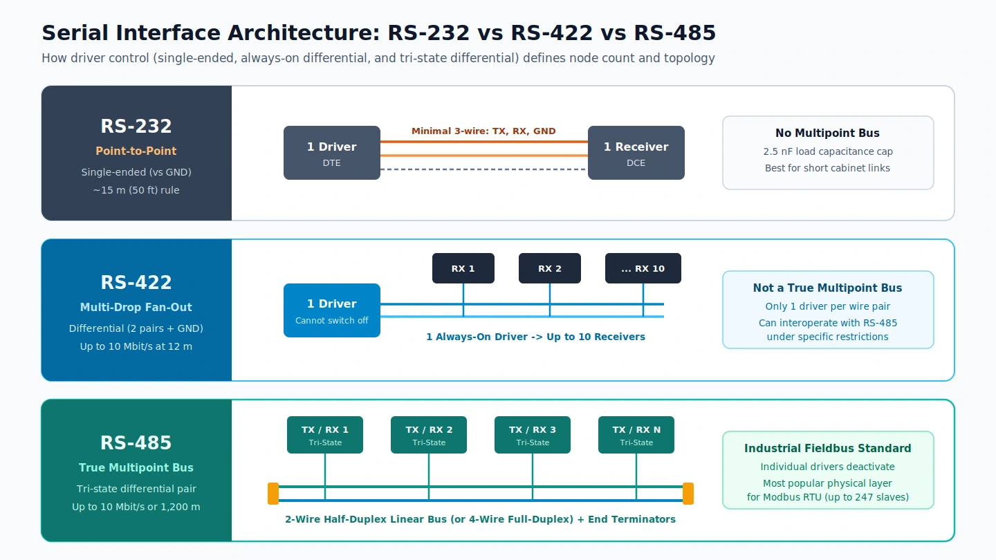
How Do RS485 and RS232 Relate to Modbus RTU vs Modbus TCP?
RS-485 specifies only the electrical characteristics of the generator and receiver at the physical layer and does not define a communications protocol. On factory floors and in PLCs, Modbus over Serial Line most commonly runs compact binary Modbus RTU over two-wire TIA/EIA-485 (supporting up to 247 slave devices with one master), whereas Modbus TCP transports Modbus frames over Ethernet TCP/IP on port 502 without a serial checksum.
| Protocol Dimension | Modbus RTU (Modbus over Serial Line) | Modbus TCP (Modbus TCP/IP) |
|---|---|---|
| Underlying physical / transport layer | RS-485 (two-wire TIA/EIA-485 most popular; four-wire RS-485 and TIA/EIA-232-E also used) | Ethernet TCP/IP network connecting over port 502 |
| Encoding and error checking | Compact binary representation followed by a cyclic redundancy check (CRC) checksum | Binary framing over TCP/IP; omits serial checksum because lower layers provide checksum protection |
| Addressing model | 1 master communicating with up to 247 slave devices (unique addresses 1 to 247) | IP-addressed TCP/IP network endpoints |
| Maximum PDU / ADU size | 253-byte max PDU; 256-byte max ADU on RS-232/RS-485 serial networks | 253-byte max PDU; 260-byte max ADU over TCP |
Because RS-232 is point-to-point, running Modbus RTU on TIA/EIA-232-E fits a single short local instrument link, while two-wire TIA/EIA-485 serves as the dominant physical layer for polling daisy-chained PLC field devices before an edge gateway bridges them onto plant Ethernet networks.
RS-485 Daisy-Chain Wiring, Termination, and Ground Reference Checklist
Before powering up a new serial trunk or troubleshooting intermittent framing errors, verify each physical-layer item in order:
- Confirm linear daisy-chain routing: Eliminate junction-box star splits and long stubs discouraged by TSB-89A; route the twisted pair continuously from node to node.
- Terminate both physical ends only: Install a termination resistor matched to cable characteristic impedance (typically 120 ohms for twisted pairs) across A and B at the two physical ends of the trunk, with pull-up and pull-down biasing resistors configured for silent idle lines.
- Verify A/B polarity across mixed connectors: Because RS-485 specifies no universal connector or pinout, confirm that logic 1 (mark) keeps A negative relative to B and logic 0 (space) keeps A positive relative to B at every screw terminal or D-subminiature plug.
- Land the SC common reference safely: Provide the TIA-485 common return path (SC or G) along the balanced line, and add current limiting on long runs between buildings where ground voltages may differ.
- Audit cable copper and shielding: Use pure-copper twisted-pair cabling rather than non-compliant CCA cable, and maintain continuous cable shielding via a drain wire in high-EMI factory zones.