A Basic Safety Message (BSM) belongs to the SAE J2735 Standard and is a frequently transmitted “heartbeat” message (usually at approximately 10Hz) meant to increase a vehicle’s situational awareness. Periodic basic safety messages (BSM) with PHY layer overheads typically measure around 300 bytes with the full security certificate header and are expected to be transmitted up to once every 100 ms. A typical BSM contains up to two parts: Part I, the binary large object (blob), is included in every BSM and contains the fundamental data elements describing a vehicle’s position (latitude, longitude, elevation) and motion (heading, speed, acceleration). Part II of a BSM contains optional data transmitted when required or in response to an event, typically serving as an extension of vehicle safety information (path history, path prediction, event flags) and vehicle component status (lights, wipers, and brakes).
For broader context across the Connected Mobility engineering guides, see what vehicle-to-everything communication covers, how vehicle-to-vehicle, infrastructure, and network paths differ, direct sidelink and dedicated short-range radio access, and how a vehicle-to-infrastructure path is described.
Protocol Stack Architecture, Broadcast Cadence, and Packet Size
Takeaway: SAE J2735 is titled V2X Communications Message Set Dictionary and defines the data and messages for DSRC (V2V, V2I, and V2D) applications, while the SAE J2945 series defines additional requirements on how to use these messages.
In the USDOT ARC-IT US: SAE Basic Safety Messages data profile, the Facilities and ITS Application Entity standards are SAE J2735 DSRC Message Set, SAE J2945 DSRC Common Design Elements, and SAE J2945/1 V2V Basic Safety. In the US: SAE Basic Safety Messages - WAVE WSMP solution, lower-layer standards support connectionless, near constant, ultra-low latency vehicle-to-any communications within ~300m using WSMP over IEEE WAVE in the 5.9GHz spectrum. In the IEEE WAVE stack, upper-layer message sublayers are composed from the SAE J2735 dictionary and J2945/1 performance requirements, with networking and transport layers based on IEEE 1609.3, security services on IEEE 1609.2, the MAC sublayer on IEEE 1609.4, and PHY and MAC layers on IEEE 802.11p.
A 3GPP Release 16 capable vehicle can communicate with another Release 14 car using the Release 14 air interface for BSM exchanges, and with other Release 16 cars using the 5G NR C-V2X air interface for advanced use cases like sensor/trajectory sharing. In C-V2X device-to-device mode (V2V, V2I, V2P), C-V2X can operate without a SIM and without network assistance, using GNSS as its primary time synchronisation source.
| Architectural dimension | Verified specification and protocol role |
|---|---|
| Message dictionary and usage rules | SAE J2735 is titled V2X Communications Message Set Dictionary and defines the data and messages for DSRC (V2V, V2I, and V2D) applications, while the SAE J2945 series defines additional requirements on how to use these messages. |
| Facilities and application entity profile | In the USDOT ARC-IT US: SAE Basic Safety Messages data profile, the Facilities and ITS Application Entity standards are SAE J2735 DSRC Message Set, SAE J2945 DSRC Common Design Elements, and SAE J2945/1 V2V Basic Safety. |
| Connectionless short messaging range | In the US: SAE Basic Safety Messages - WAVE WSMP solution, lower-layer standards support connectionless, near constant, ultra-low latency vehicle-to-any communications within ~300m using WSMP over IEEE WAVE in the 5.9GHz spectrum. |
| Layered stack composition | In the IEEE WAVE stack, upper-layer message sublayers are composed from the SAE J2735 dictionary and J2945/1 performance requirements, with networking and transport layers based on IEEE 1609.3, security services on IEEE 1609.2, the MAC sublayer on IEEE 1609.4, and PHY and MAC layers on IEEE 802.11p. |
| Heartbeat cadence and situational role | A Basic Safety Message (BSM) belongs to the SAE J2735 Standard and is a frequently transmitted “heartbeat” message (usually at approximately 10Hz) meant to increase a vehicle’s situational awareness. |
| Packet size and transmission interval | Periodic basic safety messages (BSM) with PHY layer overheads typically measure around 300 bytes with the full security certificate header and are expected to be transmitted up to once every 100 ms. |
| Direct sidelink backward compatibility | A 3GPP Release 16 capable vehicle can communicate with another Release 14 car using the Release 14 air interface for BSM exchanges, and with other Release 16 cars using the 5G NR C-V2X air interface for advanced use cases like sensor/trajectory sharing. |
| Out-of-coverage timing source | In C-V2X device-to-device mode (V2V, V2I, V2P), C-V2X can operate without a SIM and without network assistance, using GNSS as its primary time synchronisation source. |
Mandatory Basic Safety Message Part One Vehicle State Elements
Takeaway: Under SAE J2945/1 minimum criteria for BSM transmission, BSM Part 1 data elements include Time (UTC time), Message Count (random starting time), Temporary ID (randomized every 5 min), Position (Latitude, Longitude, Elevation), Positional Accuracy, Transmission State, Speed, Heading, Steering Wheel Angle, Acceleration, Brake System Status, and Vehicle Size.
A typical BSM contains up to two parts: Part I, the binary large object (blob), is included in every BSM and contains the fundamental data elements describing a vehicle’s position (latitude, longitude, elevation) and motion (heading, speed, acceleration).
Sequence Numbering, Temporary Identifier, and Timestamp
In the SAE J2735 BSM Part I (coreData_msgCnt), Message count data provides a sequence number in the range 0-127 within a stream of messages with the same DSRCmsgID and from the same sender, where the value after 127 is zero. In the SAE J2735 BSM Part I (coreData_id), TemporaryID is a 4 octet random device identifier that changes periodically on a mobile OBU device to ensure vehicle anonymity, whereas infrastructure devices (RSUs) may have a fixed value. In the SAE J2735 BSM Part I (coreData_secMark), Second Mark represents the milliseconds within a minute in units of milliseconds, where 65535 shall represent an unavailable value and values from 61000 to 65534 are reserved.
Geodetic Position and Positional Accuracy Ellipsoid
In the SAE J2735 BSM Part I (coreData_lat), geographic latitude of the vehicle is expressed in units of 1/10th microdegrees with reference to the horizontal datum then in use, and the value 900000001 shall be used when unavailable. In the SAE J2735 BSM Part I (coreData_long), geographic longitude of the vehicle is expressed in units of 1/10th microdegrees with reference to the horizontal datum then in use, and the value 1800000001 shall be used when unavailable. In the SAE J2735 BSM Part I (coreData_elev), elevation above or below the reference ellipsoid (typically WGS-84) is expressed in 10cm steps, where any elevation higher than +6143.9 meters is represented as +61439, any elevation lower than -409.5 meters is represented as -4095, and unknown elevation is encoded with -4096.
In the SAE J2735 BSM Part I (coreData_accuracy_semiMajor and coreData_accuracy_semiMinor), positional accuracy of the semi-major and semi-minor axes of the GNSS error ellipsoid is expressed in 5 cm steps (typically at a one sigma level of confidence), where 254 is used for values equal or greater than 12.70 m and 255 is used for unavailable. In the SAE J2735 BSM Part I (coreData_accuracy_orientation), positional accuracy of the semi-major axis orientation is expressed in 360/65535 degree (0.0054932479 degree) units, with a value of 65535 used for orientation unavailable.
Transmission State, Speed, Heading, and Steering Wheel Angle
In the SAE J2735 BSM Part I (coreData_transmission), Transmission state reports the current state of the vehicle transmission as neutral, park, forwardGears, reverseGears, reserved1, reserved2, reserved3, or unavailable. In the USDOT AMCD BSM schema (transmission_state), the vehicle transmission state known to the OBU when the BSM was generated is encoded as 0 = Neutral, 1 = Park, 2 = Forward, 3 = Reverse, 4 = Reserved, 5 = Reserved, 6 = Reserved, and 7 = Unavailable.
In the SAE J2735 BSM Part I (coreData_speed), vehicle speed is expressed in unsigned units of 0.02 meters per second, and a value of 8191 shall be used when the speed is unavailable. In the SAE J2735 BSM Part I (coreData_heading), heading of the sending device is expressed in unsigned units of 0.0125 degrees from North (where 28799 such degrees represent 359.9875 degrees and east is positive), and a value of 28800 shall be used when unavailable. In the SAE J2735 BSM Part I (coreData_angle), the angle of the driver’s steering wheel is expressed in 1.5 degrees, where +126 is used for +189 degrees and beyond and +127 is used for unavailable.
Four-Way Acceleration Set, Brake System Status, and Vehicle Size
In the SAE J2735 BSM Part I (coreData_accelset_long and coreData_accelset_lat), longitudinal and lateral accelerations are expressed in 0.01 m/s^2 (positive forward and positive right), where 2000 is used for values greater than 2000, -2000 for values less than -2000, and 2001 for Unavailable. In the SAE J2735 BSM Part I (coreData_accelset_vert and coreData_accelset_yaw), vertical acceleration is expressed in 0.02 G (0.02 G = 0.1962 m/s^2, positive downward, +127 for >= 2.54 G, -126 for <= 2.52 G, -127 for Unavailable), and yaw rotation rate about the vertical axis is in 0.01 degrees per second (positive clockwise).
In the USDOT AMCD BSM schema, Brake Applied Status is a bit field indicating wheel brake application (0000 = All off, 0001 = Left front active, 0010 = Left rear active, 0100 = Right front active, 1000 = Right rear active, 1111 = Brake is active), while Traction Control State and ABS Active use 0 = Unavailable, 1 = Off, 2 = On, 3 = Engaged. In the SAE J2735 BSM Part I (coreData_size), vehicle size represents the vehicle length and vehicle width in cm.
| Core vehicle state element | Scaling unit, valid range, and unavailable sentinel encoding |
|---|---|
| Message count | In the SAE J2735 BSM Part I (coreData_msgCnt), Message count data provides a sequence number in the range 0-127 within a stream of messages with the same DSRCmsgID and from the same sender, where the value after 127 is zero. |
| Temporary device identifier | In the SAE J2735 BSM Part I (coreData_id), TemporaryID is a 4 octet random device identifier that changes periodically on a mobile OBU device to ensure vehicle anonymity, whereas infrastructure devices (RSUs) may have a fixed value. |
| Second mark timestamp | In the SAE J2735 BSM Part I (coreData_secMark), Second Mark represents the milliseconds within a minute in units of milliseconds, where 65535 shall represent an unavailable value and values from 61000 to 65534 are reserved. |
| Geodetic latitude | In the SAE J2735 BSM Part I (coreData_lat), geographic latitude of the vehicle is expressed in units of 1/10th microdegrees with reference to the horizontal datum then in use, and the value 900000001 shall be used when unavailable. |
| Geodetic longitude | In the SAE J2735 BSM Part I (coreData_long), geographic longitude of the vehicle is expressed in units of 1/10th microdegrees with reference to the horizontal datum then in use, and the value 1800000001 shall be used when unavailable. |
| Ellipsoidal elevation | In the SAE J2735 BSM Part I (coreData_elev), elevation above or below the reference ellipsoid (typically WGS-84) is expressed in 10cm steps, where any elevation higher than +6143.9 meters is represented as +61439, any elevation lower than -409.5 meters is represented as -4095, and unknown elevation is encoded with -4096. |
| Horizontal error ellipse axes | In the SAE J2735 BSM Part I (coreData_accuracy_semiMajor and coreData_accuracy_semiMinor), positional accuracy of the semi-major and semi-minor axes of the GNSS error ellipsoid is expressed in 5 cm steps (typically at a one sigma level of confidence), where 254 is used for values equal or greater than 12.70 m and 255 is used for unavailable. |
| Error ellipse orientation | In the SAE J2735 BSM Part I (coreData_accuracy_orientation), positional accuracy of the semi-major axis orientation is expressed in 360/65535 degree (0.0054932479 degree) units, with a value of 65535 used for orientation unavailable. |
| Transmission state labels | In the SAE J2735 BSM Part I (coreData_transmission), Transmission state reports the current state of the vehicle transmission as neutral, park, forwardGears, reverseGears, reserved1, reserved2, reserved3, or unavailable. |
| Transmission state integer codes | In the USDOT AMCD BSM schema (transmission_state), the vehicle transmission state known to the OBU when the BSM was generated is encoded as 0 = Neutral, 1 = Park, 2 = Forward, 3 = Reverse, 4 = Reserved, 5 = Reserved, 6 = Reserved, and 7 = Unavailable. |
| Vehicle speed | In the SAE J2735 BSM Part I (coreData_speed), vehicle speed is expressed in unsigned units of 0.02 meters per second, and a value of 8191 shall be used when the speed is unavailable. |
| Vehicle heading | In the SAE J2735 BSM Part I (coreData_heading), heading of the sending device is expressed in unsigned units of 0.0125 degrees from North (where 28799 such degrees represent 359.9875 degrees and east is positive), and a value of 28800 shall be used when unavailable. |
| Steering wheel angle | In the SAE J2735 BSM Part I (coreData_angle), the angle of the driver’s steering wheel is expressed in 1.5 degrees, where +126 is used for +189 degrees and beyond and +127 is used for unavailable. |
| Longitudinal and lateral acceleration | In the SAE J2735 BSM Part I (coreData_accelset_long and coreData_accelset_lat), longitudinal and lateral accelerations are expressed in 0.01 m/s^2 (positive forward and positive right), where 2000 is used for values greater than 2000, -2000 for values less than -2000, and 2001 for Unavailable. |
| Vertical acceleration and yaw rate | In the SAE J2735 BSM Part I (coreData_accelset_vert and coreData_accelset_yaw), vertical acceleration is expressed in 0.02 G (0.02 G = 0.1962 m/s^2, positive downward, +127 for >= 2.54 G, -126 for <= 2.52 G, -127 for Unavailable), and yaw rotation rate about the vertical axis is in 0.01 degrees per second (positive clockwise). |
| Wheel brakes and stability states | In the USDOT AMCD BSM schema, Brake Applied Status is a bit field indicating wheel brake application (0000 = All off, 0001 = Left front active, 0010 = Left rear active, 0100 = Right front active, 1000 = Right rear active, 1111 = Brake is active), while Traction Control State and ABS Active use 0 = Unavailable, 1 = Off, 2 = On, 3 = Engaged. |
| Vehicle length and width | In the SAE J2735 BSM Part I (coreData_size), vehicle size represents the vehicle length and vehicle width in cm. |
Optional and Event-Driven Basic Safety Message Part Two Extensions
Takeaway: Under SAE J2945/1 minimum criteria for BSM Part II Vehicle Safety Extension, the system shall set the Hard Braking event flag when the corresponding event condition is met (see SAE J2735), sets the ABS, Traction Control, and Stability Control event flags when those conditions occur (if available), and includes Path History (15 points max), Path Prediction (radius and confidence), and Exterior Lights.
Part II of a BSM contains optional data transmitted when required or in response to an event, typically serving as an extension of vehicle safety information (path history, path prediction, event flags) and vehicle component status (lights, wipers, and brakes).
Vehicle Safety Extensions: Event Flags, Path History, Path Prediction, and Exterior Lights
In the SAE J2735 BSM Part Two Vehicle Safety Extension (part2_vse_events), Vehicle event flags are encoded as a bit string including eventHazardLights, eventStopLineViolation, eventABSactivated, eventTractionControlLoss, eventStabilityControlactivated, eventHazardousMaterials, eventReserved1, eventHardBraking, eventLightsChanged, eventWipersChanged, eventFlatTire, eventDisabledVehicle, and eventAirBagDeployment.
In the SAE J2735 BSM Part Two Vehicle Safety Extension (part2_vse_ph_crumbdata), Path History defines a geometric path reflecting time-tagged vehicle movement over a period of time and/or distance using a sequence of Path History Points with lat-long offsets in units of 1/10th micro degrees, elevation offsets in 10cm units, and time in units of 10 milliseconds. In the SAE J2735 BSM Part Two Vehicle Safety Extension (part2_vse_pp_confidence and part2_vse_pp_radiusofcurve), Path Prediction confidence is expressed in units of 0.5 percent, and Path Prediction radius of curve is a first-order curvature approximation circle radius R in units of 10cm (positive for curvatures to the right, and 32767 for a straight path). In the SAE J2735 BSM Part Two Vehicle Safety Extension (part2_vse_lights), Exterior Lights encodes the status of exterior lights in a bit string ordered as: lowBeamHeadlightsOn, highBeamHeadlightsOn, leftTurnSignalOn, rightTurnSignalOn, hazardSignalOn, automaticLightControlOn, daytimeRunningLightsOn, fogLightOn, parkingLightsOn.
Supplemental Vehicle Extensions: Classification, Role, Dimensions, and Vehicle Mass
In the SAE J2735 BSM Part Two Supplemental Vehicle Extension (part2_suve_classification, part2_suve_cd_hpmstype, and part2_suve_cd_role), fields categorize the basic vehicle class, the US DOT Highway Performance Monitoring System (HPMS) vehicle size type, and the BasicVehicleRole (such as role “police” when a police car sends a signal request message SRM with a matching security CERT SSP, or role “transit”). In the SAE J2735 BSM Part Two Supplemental Vehicle Extension (part2_suve_vd_height, part2_suve_vd_bumpers_front, and part2_suve_vd_bumpers_rear), vehicle height from the ground to the highest surface (excluding antennas) is expressed in units of 5 cm, and front and rear bumper heights are expressed in units of 0.01 meters from the ground surface. In the SAE J2735 BSM Part Two Supplemental Vehicle Extension (part2_suve_vd_mass), estimated vehicle mass is encoded over stepwise linear values from zero to in excess of 170000 kg: values 000 to 080 in steps of 50kg, values 081 to 200 in steps of 500kg, values 201 to 253 in steps of 2000kg, 254 for weights above 170000 kg, and 255 when unknown or unavailable.
| Optional extension container | Trigger criteria, bit strings, and scaling resolution |
|---|---|
| Minimum safety extension triggers | Under SAE J2945/1 minimum criteria for BSM Part II Vehicle Safety Extension, the system shall set the Hard Braking event flag when the corresponding event condition is met (see SAE J2735), sets the ABS, Traction Control, and Stability Control event flags when those conditions occur (if available), and includes Path History (15 points max), Path Prediction (radius and confidence), and Exterior Lights. |
| Vehicle event flags bit string | In the SAE J2735 BSM Part Two Vehicle Safety Extension (part2_vse_events), Vehicle event flags are encoded as a bit string including eventHazardLights, eventStopLineViolation, eventABSactivated, eventTractionControlLoss, eventStabilityControlactivated, eventHazardousMaterials, eventReserved1, eventHardBraking, eventLightsChanged, eventWipersChanged, eventFlatTire, eventDisabledVehicle, and eventAirBagDeployment. |
| Path history crumb offsets | In the SAE J2735 BSM Part Two Vehicle Safety Extension (part2_vse_ph_crumbdata), Path History defines a geometric path reflecting time-tagged vehicle movement over a period of time and/or distance using a sequence of Path History Points with lat-long offsets in units of 1/10th micro degrees, elevation offsets in 10cm units, and time in units of 10 milliseconds. |
| Path prediction curvature and confidence | In the SAE J2735 BSM Part Two Vehicle Safety Extension (part2_vse_pp_confidence and part2_vse_pp_radiusofcurve), Path Prediction confidence is expressed in units of 0.5 percent, and Path Prediction radius of curve is a first-order curvature approximation circle radius R in units of 10cm (positive for curvatures to the right, and 32767 for a straight path). |
| Exterior lights bit string order | In the SAE J2735 BSM Part Two Vehicle Safety Extension (part2_vse_lights), Exterior Lights encodes the status of exterior lights in a bit string ordered as: lowBeamHeadlightsOn, highBeamHeadlightsOn, leftTurnSignalOn, rightTurnSignalOn, hazardSignalOn, automaticLightControlOn, daytimeRunningLightsOn, fogLightOn, parkingLightsOn. |
| Vehicle class and operational role | In the SAE J2735 BSM Part Two Supplemental Vehicle Extension (part2_suve_classification, part2_suve_cd_hpmstype, and part2_suve_cd_role), fields categorize the basic vehicle class, the US DOT Highway Performance Monitoring System (HPMS) vehicle size type, and the BasicVehicleRole (such as role “police” when a police car sends a signal request message SRM with a matching security CERT SSP, or role “transit”). |
| Vehicle and bumper vertical dimensions | In the SAE J2735 BSM Part Two Supplemental Vehicle Extension (part2_suve_vd_height, part2_suve_vd_bumpers_front, and part2_suve_vd_bumpers_rear), vehicle height from the ground to the highest surface (excluding antennas) is expressed in units of 5 cm, and front and rear bumper heights are expressed in units of 0.01 meters from the ground surface. |
| Stepwise linear vehicle mass | In the SAE J2735 BSM Part Two Supplemental Vehicle Extension (part2_suve_vd_mass), estimated vehicle mass is encoded over stepwise linear values from zero to in excess of 170000 kg: values 000 to 080 in steps of 50kg, values 081 to 200 in steps of 500kg, values 201 to 253 in steps of 2000kg, 254 for weights above 170000 kg, and 255 when unknown or unavailable. |
Payload Scope Boundary: Ego Vehicle Broadcast Versus Other Message Types
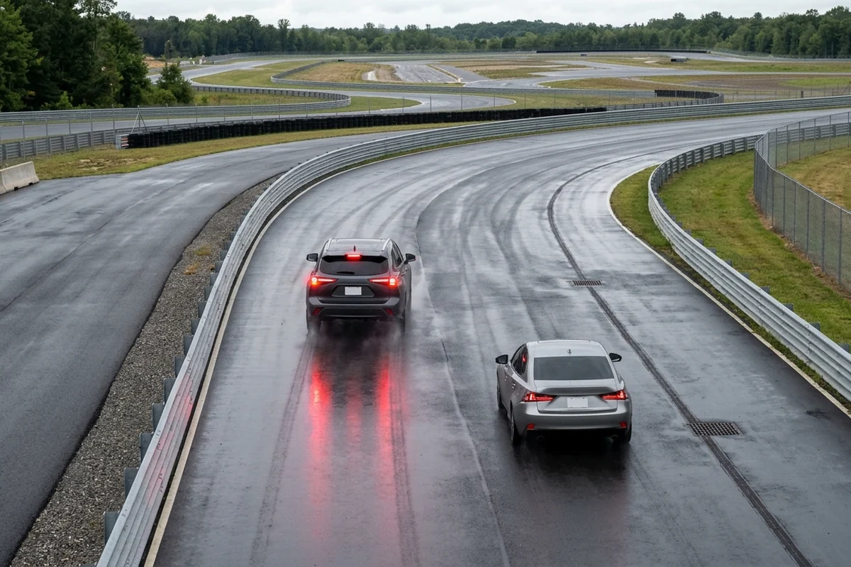
Takeaway: In the SAE J2735 data dictionary overview, there are 16 Messages (plus 16 test messages), 156 Data Frames, 231 Data Elements, ~58 External Elements, ~65 places where regional content can be inserted without coordination with others, and ~526 reusable data concepts, where BasicSafetyMessage (BSM) is distinct from MapData (MAP), SignalPhaseAndTiming Message (SPAT), SignalRequestMessage (SRM), SignalStatusMessage (SSM), TravelerInformation Message (TIM), ProbeVehicleData (PVD), and RoadSideAlert (RSA).
In the USDOT MMITSS Basic Safety Message dataset documentation, extra attachments such as MAP, Detectors, and Simulation results are located in the Multi-Modal Intelligent Traffic Signal Systems Basic Safety Messages dataset. SAE J3186 (Ed. 1, published 23/03/2023), Application Protocol and Requirements for Maneuver Sharing and Coordinating Service, provides requirements to support applications for the maneuver sharing and coordinating service (MSCS) beyond broadcast of basic safety messages (BSMs) via vehicle-to-everything (V2X) communications, resulting in identifying new message types, data frames, and data elements for SAE J2735. ADASIS V3 (version 3.2.1, ADAS Interface Specification v3 Protocol, published 11/05/2023) defines the concept of an ADAS Horizon to convey the part of the road network and its characteristics originating from map data along the road ahead of the vehicle, constructed as a hierarchy of possible paths through the road network and serialized over the vehicle communication network.
| Message family or specification | Functional boundary relative to Basic Safety Message records |
|---|---|
| Dictionary message separation | In the SAE J2735 data dictionary overview, there are 16 Messages (plus 16 test messages), 156 Data Frames, 231 Data Elements, ~58 External Elements, ~65 places where regional content can be inserted without coordination with others, and ~526 reusable data concepts, where BasicSafetyMessage (BSM) is distinct from MapData (MAP), SignalPhaseAndTiming Message (SPAT), SignalRequestMessage (SRM), SignalStatusMessage (SSM), TravelerInformation Message (TIM), ProbeVehicleData (PVD), and RoadSideAlert (RSA). |
| Multi-modal signal dataset storage | In the USDOT MMITSS Basic Safety Message dataset documentation, extra attachments such as MAP, Detectors, and Simulation results are located in the Multi-Modal Intelligent Traffic Signal Systems Basic Safety Messages dataset. |
| Cooperative maneuver negotiation | SAE J3186 (Ed. 1, published 23/03/2023), Application Protocol and Requirements for Maneuver Sharing and Coordinating Service, provides requirements to support applications for the maneuver sharing and coordinating service (MSCS) beyond broadcast of basic safety messages (BSMs) via vehicle-to-everything (V2X) communications, resulting in identifying new message types, data frames, and data elements for SAE J2735. |
| In-vehicle map horizon serialization | ADASIS V3 (version 3.2.1, ADAS Interface Specification v3 Protocol, published 11/05/2023) defines the concept of an ADAS Horizon to convey the part of the road network and its characteristics originating from map data along the road ahead of the vehicle, constructed as a hierarchy of possible paths through the road network and serialized over the vehicle communication network. |
Safety Applications, Field Pilots, and On-Board Hardware Execution
Takeaway: In the USDOT Tampa CV Pilot, Basic Safety Messages (BSMs) are generated by participant and public transportation vehicle onboard units (OBUs) and transmitted to road-side units (RSUs) throughout the study area, with data fields following SAE J2735 and J2945/1 standards.
Cooperative Collision Warnings and Crash Mitigation Scope
DSRC V2V safety use cases tested at the Ann Arbor Safety Pilot include Emergency Electronic Brake Lights (EEBL, where brake “on” from several cars ahead is sent to the subject vehicle) and Forward Collision Warning (FCW, an alert to elicit hard braking to prevent a rear-end crash). Additional DSRC V2V safety use cases tested at the Ann Arbor Safety Pilot include Blind Spot Warning/Lane Change Warning (BSW/LCW, alerts of fast-approaching cars from behind and in adjoining lanes), Do Not Pass Warning (DNPW, alerts for head-on crashes during a passing maneuver), Intersection Movement Assist (IMA), and Left Turn Assist (LTA). According to Cohda Wireless, the US Department of Transport estimates 94% of crashes involve human error, and V2X has the potential to eliminate or mitigate up to 80% of non-impaired-driving collisions.
Field Pilot Datasets and Urban Canyon Ranging Localization
In the USDOT Tampa CV Pilot, Basic Safety Messages (BSMs) are generated by participant and public transportation vehicle onboard units (OBUs) and transmitted to road-side units (RSUs) throughout the study area, with data fields following SAE J2735 and J2945/1 standards. In the USDOT Advanced Messaging Concept Development (AMCD) field testing program, all Part I BSM message fields were populated, and all BSMs were generated by OBUs and ultimately received by the VCC Cloud server. In GNSS-challenged locations such as urban canyons, tunnels, and parking garages, Cohda Wireless V2X-Locate uses ranging measurements from spatially separated fixed RSUs to position vehicles equipped with OBUs with accuracy <1m 95% of the time.
On-Board Unit Hardware Architecture and Vehicle Bus Interfaces
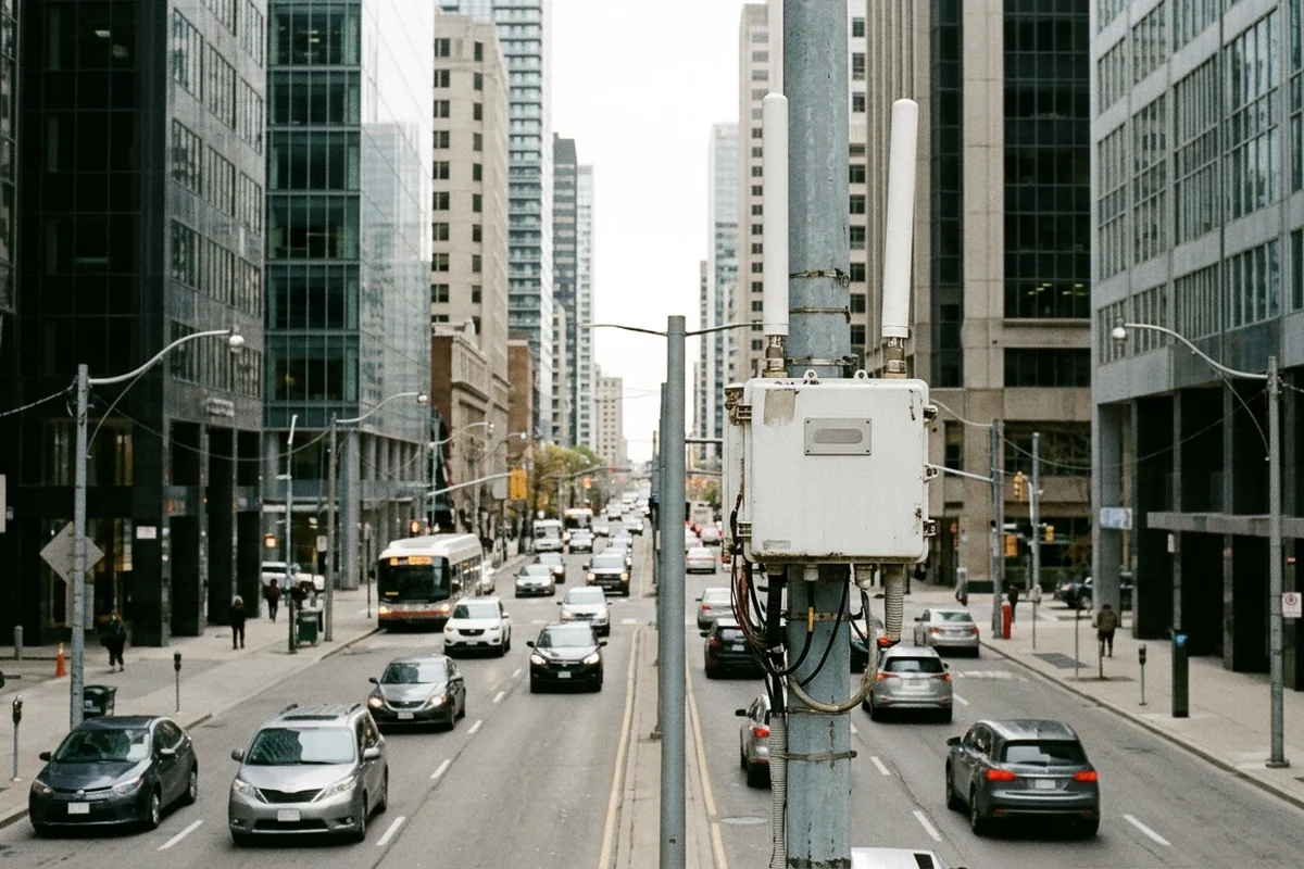
The Cohda Wireless MK6 OBU lists V2X test standard conformance for IEEE 802.11-2012, IEEE 1609-2020, ETSI ES 202 663, SAE J2735-2020, SAE J3161/1, J3161/1A, J3161-2022, and T/CSAE-2021, and includes Advanced GNSS with RTK capability, SXF1800 FIPS 140-2 security, and high speed CAN-FD up to 5Mbit/sec. The Kapsch CBX-9360 C-V2X Onboard Communication Unit supports ITS communication standards LTE-V2X 3GPP Rel.14, SAE J2735 2016 / 2020, and the IEEE WAVE standard set, operating in the 5.850 to 5.925GHz band with 20 (/10) MHz channel spacing, Multi-GNSS (GPS, GLONASS, Galileo, BeiDou), and a FIPS 140-2 level 3 / CC EAL4+ Hardware Security Module.
| Application or hardware platform | Verified field execution and interface characteristics |
|---|---|
| Longitudinal braking warnings | DSRC V2V safety use cases tested at the Ann Arbor Safety Pilot include Emergency Electronic Brake Lights (EEBL, where brake “on” from several cars ahead is sent to the subject vehicle) and Forward Collision Warning (FCW, an alert to elicit hard braking to prevent a rear-end crash). |
| Lateral, passing, and intersection warnings | Additional DSRC V2V safety use cases tested at the Ann Arbor Safety Pilot include Blind Spot Warning/Lane Change Warning (BSW/LCW, alerts of fast-approaching cars from behind and in adjoining lanes), Do Not Pass Warning (DNPW, alerts for head-on crashes during a passing maneuver), Intersection Movement Assist (IMA), and Left Turn Assist (LTA). |
| Urban canyon ranging localization | In GNSS-challenged locations such as urban canyons, tunnels, and parking garages, Cohda Wireless V2X-Locate uses ranging measurements from spatially separated fixed RSUs to position vehicles equipped with OBUs with accuracy <1m 95% of the time. |
| Transit and participant corridor pilot | In the USDOT Tampa CV Pilot, Basic Safety Messages (BSMs) are generated by participant and public transportation vehicle onboard units (OBUs) and transmitted to road-side units (RSUs) throughout the study area, with data fields following SAE J2735 and J2945/1 standards. |
| Sixth-generation onboard unit | The Cohda Wireless MK6 OBU lists V2X test standard conformance for IEEE 802.11-2012, IEEE 1609-2020, ETSI ES 202 663, SAE J2735-2020, SAE J3161/1, J3161/1A, J3161-2022, and T/CSAE-2021, and includes Advanced GNSS with RTK capability, SXF1800 FIPS 140-2 security, and high speed CAN-FD up to 5Mbit/sec. |
| Cellular onboard communication unit | The Kapsch CBX-9360 C-V2X Onboard Communication Unit supports ITS communication standards LTE-V2X 3GPP Rel.14, SAE J2735 2016 / 2020, and the IEEE WAVE standard set, operating in the 5.850 to 5.925GHz band with 20 (/10) MHz channel spacing, Multi-GNSS (GPS, GLONASS, Galileo, BeiDou), and a FIPS 140-2 level 3 / CC EAL4+ Hardware Security Module. |
Basic Safety Message Field Structure Verification Checklist
Takeaway: In the USDOT Advanced Messaging Concept Development (AMCD) field testing program, all Part I BSM message fields were populated, and all BSMs were generated by OBUs and ultimately received by the VCC Cloud server.
| Verification checkpoint | Engineering criterion to confirm in telemetry logs |
|---|---|
| Packet size and certificate cadence | Periodic basic safety messages (BSM) with PHY layer overheads typically measure around 300 bytes with the full security certificate header and are expected to be transmitted up to once every 100 ms. |
| Mandatory core blob completeness | Under SAE J2945/1 minimum criteria for BSM transmission, BSM Part 1 data elements include Time (UTC time), Message Count (random starting time), Temporary ID (randomized every 5 min), Position (Latitude, Longitude, Elevation), Positional Accuracy, Transmission State, Speed, Heading, Steering Wheel Angle, Acceleration, Brake System Status, and Vehicle Size. |
| Second mark reserved and unavailable codes | In the SAE J2735 BSM Part I (coreData_secMark), Second Mark represents the milliseconds within a minute in units of milliseconds, where 65535 shall represent an unavailable value and values from 61000 to 65534 are reserved. |
| Latitude unavailable sentinel | In the SAE J2735 BSM Part I (coreData_lat), geographic latitude of the vehicle is expressed in units of 1/10th microdegrees with reference to the horizontal datum then in use, and the value 900000001 shall be used when unavailable. |
| Longitude unavailable sentinel | In the SAE J2735 BSM Part I (coreData_long), geographic longitude of the vehicle is expressed in units of 1/10th microdegrees with reference to the horizontal datum then in use, and the value 1800000001 shall be used when unavailable. |
| Speed scaling and unavailable sentinel | In the SAE J2735 BSM Part I (coreData_speed), vehicle speed is expressed in unsigned units of 0.02 meters per second, and a value of 8191 shall be used when the speed is unavailable. |
| Safety extension event and path triggers | Under SAE J2945/1 minimum criteria for BSM Part II Vehicle Safety Extension, the system shall set the Hard Braking event flag when the corresponding event condition is met (see SAE J2735), sets the ABS, Traction Control, and Stability Control event flags when those conditions occur (if available), and includes Path History (15 points max), Path Prediction (radius and confidence), and Exterior Lights. |
| Stepwise mass encoding tiers | In the SAE J2735 BSM Part Two Supplemental Vehicle Extension (part2_suve_vd_mass), estimated vehicle mass is encoded over stepwise linear values from zero to in excess of 170000 kg: values 000 to 080 in steps of 50kg, values 081 to 200 in steps of 500kg, values 201 to 253 in steps of 2000kg, 254 for weights above 170000 kg, and 255 when unknown or unavailable. |
| Separation from map and signal messages | In the SAE J2735 data dictionary overview, there are 16 Messages (plus 16 test messages), 156 Data Frames, 231 Data Elements, ~58 External Elements, ~65 places where regional content can be inserted without coordination with others, and ~526 reusable data concepts, where BasicSafetyMessage (BSM) is distinct from MapData (MAP), SignalPhaseAndTiming Message (SPAT), SignalRequestMessage (SRM), SignalStatusMessage (SSM), TravelerInformation Message (TIM), ProbeVehicleData (PVD), and RoadSideAlert (RSA). |
Sources
- Society of Automotive Engineers — Connected Vehicle Communications Message Set Dictionary and Basic Safety Specifications
- United States Department of Transportation — Cooperative and Intelligent Transportation Architecture Reference
- United States Department of Transportation (Data.gov / ITS JPO) — MMITSS Basic Safety Message
- Qualcomm Technologies — Introduction to Cellular Vehicle-to-Everything Technical Reference
- Fifth Generation Automotive Association — Cellular Vehicle-to-Everything Direct Communication Reference
- Connected Automated Driving Europe — Cooperative Connected and Automated Mobility Technical Reference
- Cohda Wireless — Connected Vehicle Software Stack and On-Board Unit Technical Reference
- Kapsch TrafficCom — Onboard Communication Unit Technical Data Sheet