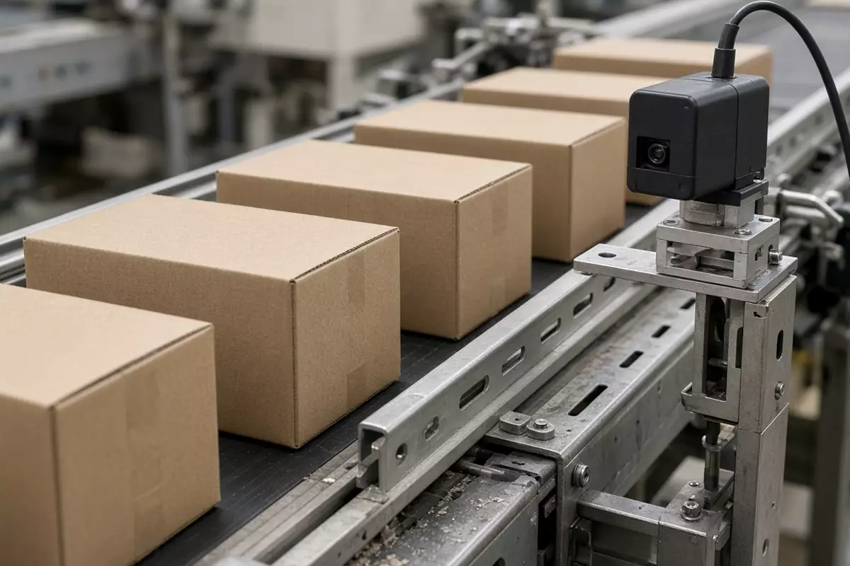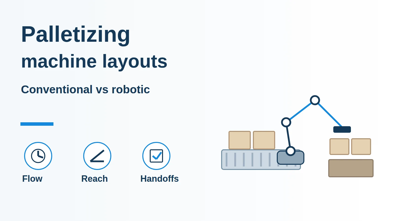
A missing pallet-exchange path can block a packaging line even when its load-building mechanism fits. Compare a conventional palletizing machine’s layer-forming layout with a robotic palletizing machine’s pick-and-place layout, then draw pallet supply, discharge and service access around each.
A conventional layout needs a route through pattern formation and layer transfer; a robotic layout needs reachable pickup and placement positions. Compare both against the same product, finished load and exchange boundary. The mechanism alone does not establish the complete installed space or sustainable output. Begin with the signals and acceptance boundary in case packing and palletizing integration, then use the layout checks below to identify unresolved interfaces.
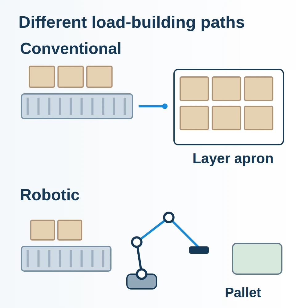
What actually changes between the layouts?
The load-building path changes first. Scott’s published description routes conventional cases through turning and row formation onto an apron, which withdraws to deposit the layer. Its robotic description uses an arm and end-of-arm tooling; pickup positions can differ in elevation and location within operating reach.
| Input or item | Typical value or source | Why it matters |
|---|---|---|
| Conventional product path | Scott: infeed, turning, row formation, apron | Draw the whole layer-building route |
| Robotic product path | Scott: pickup and placement using end-of-arm tooling | Locate every pickup and placement pose |
| Robot cell arrangement | Columbia/Okura: reach, inputs, outputs and available facility space | Compare complete configurations |
Columbia/Okura’s configuration guidance identifies reach and input/output space as layout drivers and notes that additional conveyors require additional space. These OEM descriptions support the mechanism comparison, rather than a universal ranking of floor area or speed.
Which physical failures should the drawing expose?
Expose the product-support and transfer points before choosing a preferred concept. The prevention checks below are engineering deductions from those documented mechanisms and require verification on the actual package.
| Layout | Drawing review | Dominant Failure Mode & Prevention |
|---|---|---|
| Conventional layer formation | Case orientation, row entry and apron transfer | A skewed or damaged case disrupts layer formation; verify guides, pattern and transfer support with the package range |
| Robotic pick and place | Tool approach, grasp, loaded travel and release | An unsuitable grasp loses or distorts the case; validate tool contact, retention and release on representative packs |
| Either complete installation | Empty pallet supply, loaded discharge and recovery access | An occupied discharge blocks production; define downstream acceptance and pallet-exchange recovery |
Put the most demanding package into the review: the case whose dimensions, closure or stiffness makes transfer difficult. A nominal pallet rectangle says little about how that case behaves at a turning point or under a gripper. Keep a separate record of package condition, orientation, tooling and observed transfer behaviour when validating the concept.
What threshold rules out an impossible load path?
Reject a load path with zero or negative geometric clearance. This is a first geometry screen; positive clearance still needs an engineered allowance for tolerances, motion and protection.
Physical threshold rule: if the unobstructed opening height minus the maximum transported load envelope is ≤ 0 mm, reject that route. For a robot, also verify every required loaded pose against its usable workspace with the actual tool and load; a nominal reach circle cannot validate a path.
Load-height formula: H_load = H_pallet + n_layers × H_case + H_sheets.
Worked example — hypothetical geometry, not a cell footprint: H_load = 150 mm + 6 × 200 mm + 0 mm = 1,350 mm. The zero sheet allowance means this example has no interlayer sheets. Substitute actual pallet, case and sheet measurements, then include overheight, load lean and handling equipment in the transported envelope where applicable.
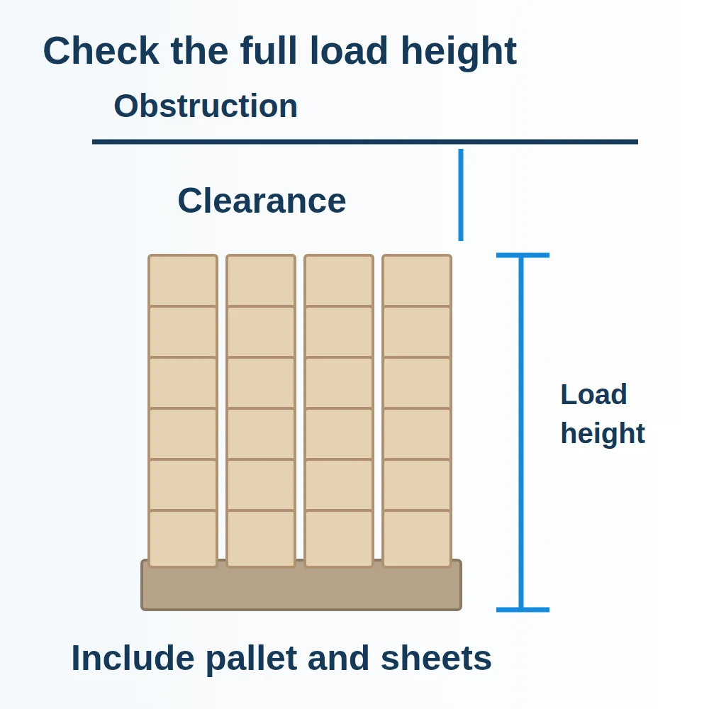
Check the final layer and tool withdrawal as well as the first pickup. Review overhead services and the transfer to wrapping or warehouse handling. Geometric clearance is not a safeguarding distance; the risk assessment and applicable safety requirements determine protective measures.
How should the time ledger compare the alternatives?
Compare the same sequence from incoming case acceptance to loaded pallet acceptance downstream. Record concurrent events so the ledger does not add the same interruption twice.
| Ledger entry | What to record | Interface to check |
|---|---|---|
| Product or pattern change | Recipe work, mechanical adjustment and first accepted load | Case and pallet handoff identity |
| Empty pallet shortage | Start/end of blocked production and replenishment labour | Buffer and blocked-state logic |
| Failed case transfer | Recovery duration, discarded cases and restart checks | Machine states |
| Loaded pallet waiting | Discharge occupancy until downstream acceptance | AMR packaging handoffs |
Time-ledger formula: elapsed interruption = sum of nonoverlapping interruption intervals.
Worked example — hypothetical planning ledger: 12 min of changeover + 8 min of pallet shortage + 5 min of transfer recovery = 25 min, only if the three intervals do not overlap. These are illustrative ledger entries, not machine cycle times or expected downtime. Keep labour, discarded packaging, replacement tooling and energy records separately when building the ownership comparison.
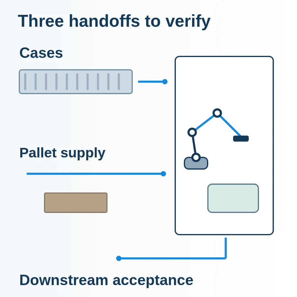
For either proposal, retain a drawing revision, package list, load-height calculation and event trace for the same operating scenario. Observe pallet replenishment, a full-load exchange, a product change and a recoverable transfer fault. The evidence should show where a case waits and how acceptance resumes, not just that the load-building motion completed.
Method and sources
Scott’s retrieved OEM page supplies the conventional apron sequence and robotic pickup description. Columbia/Okura’s retrieved OEM page supplies reach and conveyor-configuration considerations. Clearance, failure-prevention and ledger checks are engineering applications of those facts. Diagrams are conceptual, not scaled installation drawings; no cycle-rate, cell-area or saving claim is made. Updated October 2026.