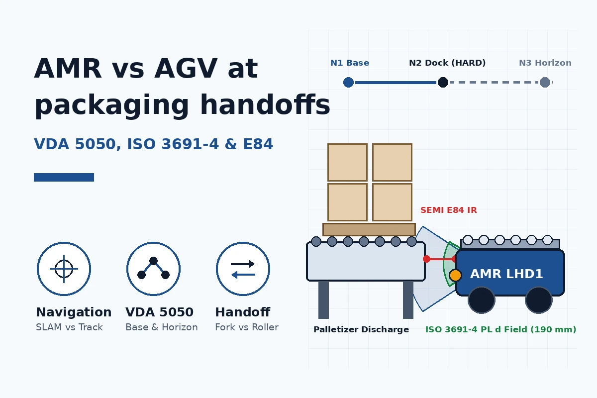
Selecting a mobile robot for an end-of-line packaging cell by its open-aisle navigation brochure without matching its docking tolerance, safety scanner field switching, and load-handling passline to the palletizer discharge causes nuisance safety trips, jammed pallet stringers, and unplanned line downtime. When evaluating AMR vs AGV architectures around case packers, palletizers, and stretch wrappers, engineers must connect the fleet interface introduced in AMR handoffs at a packaging line to four physical constraints: trajectory autonomy, 90° turning envelopes, ISO 3691-4:2023 protective field reduction, and deterministic station interlocks.
| Engineering Axis | Track-Guided AGV (Line-Guided) | SLAM AMR (Roller-Top Deck) | SLAM AMR (Forked Pallet Jack) | Dominant Failure Mode & Prevention |
|---|---|---|---|---|
| Trajectory & guidance physics (VDA 5050 v3.0) | Fixed path (MAGNETIC_TAPE, INDUCTIVE_WIRE, QR GRID, or 2D REFLECTOR triangulation) |
Natural-feature 2D/3D LiDAR SLAM (NATURAL) + station V-marker or reflector servoing |
Natural-feature 2D/3D LiDAR SLAM + 3D AI pallet-pocket vision (MiR1200) |
SLAM drift near stacked pallets: require local V-marker or 3D pocket re-acquisition over final 1.0–1.5 m |
| Open-aisle vs. station docking accuracy | ±5 to ±10 mm continuous path; ±3 to ±5 mm station stop |
±10 to ±25 mm (±1–2° yaw) in aisle; ±3 to ±5 mm (±0.5° yaw) at conveyor dock |
±10 to ±25 mm in aisle; ±5 to ±10 mm lateral (±0.5–1.0° yaw) at fork entry |
Leading pallet board jam on rollers: hold vertical step ≤ ±3–5 mm and bumper gap 15–25 mm |
| Obstacle behavior & path corridor | Stop-and-wait on guidepath (allowedDeviationXY ≈ 0.05–0.10 m) |
Dynamic local path planning inside VDA 5050 corridor (leftWidth, rightWidth) |
Dynamic local path planning in aisle; fixed straight insertion vector during fork entry | Corridor clipping during turn: size ISO 3691-4 cornering protective fields for pallet overhang |
Minimum 90° docking aisle width (VDI 2198) |
2.10 to 2.40 m (inline spur or differential spin) |
2.15 to 2.30 m (7.1–7.5 ft) for 0° spin-in-place with 1,200 × 800 mm EUR pallet |
2.80 to 3.40 m (9.2–11.2 ft) to square trailing forks into pickup bay (48 × 40 in. GMA) |
Fork tip collision with center stringer: enforce ≥ 2.80 m clear right-angle approach bay |
Station passline height & handoff time (t_handoff) |
450 to 750 mm conveyor passline (or forked); 12 to 20 s transfer |
450 to 750 mm motorized roller deck; 12 to 20 s transfer (v_roller = 0.15–0.20 m/s) |
0 mm floor or ≤ 85–110 mm open-channel stand; 35 to 60 s full fork cycle |
Palletizer blocked during slow fork cycle: add 2-pallet buffer zone or pre-stage via Horizon order |
AMR vs. AGV: what changes in navigation, aisle geometry and ISO 3691-4 safety zones
Takeaway: The engineering boundary in AMR vs AGV selection is whether the vehicle follows a pre-calibrated trajectory (±5 to ±10 mm continuous path, stop-and-wait obstacle behavior) or computes a local trajectory within a corridor (±10 to ±25 mm open-aisle SLAM) before switching to closed-loop target servoing (±3 to ±5 mm) and reduced-speed ISO 3691-4 docking fields (≤ 0.30 m/s) at the conveyor stand.
Instead of relying on commercial labels, VDA 5050 Version 3.0.0 classifies vehicles by trajectory autonomy. Section 3.6 defines a line-guided mobile robot (classical track-guided or virtual-path AGV) as a vehicle that follows predefined trajectories stored onboard or dispatched by fleet control as direct node-to-node connections. Section 3.7 defines a freely navigating mobile robot (AMR) as a vehicle that plans its own local trajectories between nodes unless constrained by an explicit trajectory or corridor object. In North America, the ANSI/RIA R15.08-1 and ANSI/A3 R15.08-2 standards further classify vehicles with active roller decks or pallet forks as Class B Industrial Mobile Robots (IMRs) and require site-specific safeguarding where those attachments interface with fixed packaging conveyors.
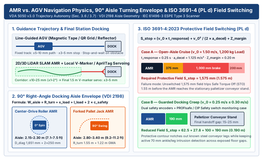
In open warehouse aisles, natural-feature 2D/3D LiDAR SLAM fuses laser scan matching with wheel encoder odometry and an inertial measurement unit (IMU), holding ±10 to ±25 mm translational accuracy and ±1° to ±2° yaw. When floor staging lanes fill with stretch-wrapped pallets and occlude more than 40% to 50% of permanent building columns or walls, map localization alone is too coarse for a mechanical conveyor transfer. To bridge that gap, the AMR switches over the final 1.0 to 1.5 m approach to closed-loop local servoing—locking its safety LiDAR or 3D camera onto a metallic station V-marker (120°–135° chevron groove), high-contrast retroreflective tape, AprilTag fiducial, or 3D pallet-pocket profile (MiR1200 Pallet Jack) to achieve ±3 to ±5 mm lateral repeatability and ±0.5° yaw.
Right-angle 90° aisle turning envelope (VDI 2198 and ISO 3691-4)
When a mobile robot turns 90° out of a main transport lane to dock at a palletizer discharge spur, the minimum physical aisle width (W_aisle) is governed by the vehicle’s outside turning radius (R_turn), load axle-to-fork-tip projection (x_load + l_load), and mandatory per-side safety clearance (c_safety):
W_aisle = R_turn + x_load + l_load + (2 × c_safety)
For a center-drive differential or omnidirectional underride robot that spins in place (R_turn = 0 mm), the swept diameter is the diagonal of the combined robot-and-pallet rectangle (D_diag = sqrt(L_env² + W_env²)):
- Worked comparison — center-drive roller-deck AMR: Carrying a
1,200 × 800 mmEUR-EPAL pallet on a1,350 × 950 mmchassis yields a diagonal swept diameterD_diag = sqrt(1,350² + 950²) = 1,651 mm(1.65 m). Adding2 × 250 mm = 500 mmlateral scanner and tracking clearance sets a minimum 90° docking aisle of2.15 to 2.30 m(7.1 to 7.5 ft). - Worked comparison — forked pallet jack AMR: Carrying a
1,219 × 1,016 mm(48 × 40 in.) GMA pallet on trailing forks (R_turn = 1,450 to 1,650 mm, load projectionx_load + l_load = 1,100 to 1,250 mm, plus2 × 250 mm = 500 mmclearance) requires a 90° right-angle aisle of2.80 to 3.40 m(9.2 to 11.2 ft) so the vehicle can square its forks parallel to the pallet pockets before insertion.
Dynamic safety field switching and stopping distance math (ISO 3691-4:2023)
Under ISO 3691-4:2023, personnel detection and emergency braking functions on driverless industrial trucks must meet Performance Level PL d (Category 3) per ISO 13849-1, implemented with Electro-Sensitive Protective Equipment (ESPE Type 3 per IEC 61496-3) such as the SICK microScan3 Pro safety laser scanner (275° scan angle, up to 128 monitoring cases). The scanner’s protective field length (S_stop) along the travel vector must exceed the vehicle’s worst-case stopping distance:
S_stop = (v_0 × t_response) + (v_0² / (2 × a_decel)) + Z_margin
Where v_0 is the safe encoder-verified travel speed (m/s), t_response is the total safety loop reaction time (scanner scan + safe PLC + brake engagement, typically 0.22 to 0.28 s), a_decel is the guaranteed loaded braking deceleration (1.0 to 1.2 m/s²), and Z_margin combines scanner measurement tolerance and ankle-probe intrusion margin (0.10 to 0.20 m).
- Open-aisle cruise (
v_0 = 1.50 m/s): Witht_response = 0.25 s,a_decel = 1.125 m/s², andZ_margin = 0.20 m, reaction travel is1.50 × 0.25 = 0.375 m(375 mm) and braking travel is1.50² / (2 × 1.125) = 1.000 m(1,000 mm), requiring a protective field ofS_stop = 1.575 m(1,575 mm). If this open-aisle field remains active as the robot approaches a stationary palletizer conveyor, the scanner detects the steel conveyor frame1.55 mbefore docking and trips an immediate Safe Torque Off (STO) fault. - Guarded station docking creep (
v_0 = 0.25 m/s ≤ 0.30 m/s): Crossing the docking threshold1.2 to 1.5 mfrom the conveyor, the safety PLC verifies deceleration tov_0 = 0.25 m/s(within the≤ 0.30 m/sreduced-speed docking limit inISO 3691-4) and switches the scanner viaPROFIsafeorCIP Safetyto a docked monitoring case. Reaction travel drops to62.5 mm, braking travel drops to27.8 mm, and with a100 mmcontoured margin the required field shrinks toS_stop = 0.190 m(190 mm) with side notches tailored around the conveyor legs, allowing the AMR to close the final15 to 25 mmtransfer gap.
How VDA 5050 splits a fleet route into Base, Horizon and station actions
Takeaway: A VDA 5050 fleet management controller prevents multi-robot deadlocks and Wi-Fi drop collisions by splitting every MQTT order into a cleared Base subgraph (released: true) and a planned Horizon subgraph (released: false), while gating physical pallet transfers with blockingType: HARD node actions at the station Decision Point.
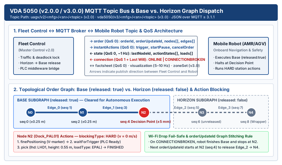
Published jointly by the VDA and VDMA, VDA 5050 Version 2.0.0 and VDA 5050 Version 3.0.0 standardize communication between a central Master Control / Fleet Control system and heterogeneous AGVs or AMRs using UTF-8 JSON payloads over an MQTT (≥ 3.1.1 or 5.0) broker. Version 2.0.0 structures topics as uagv/v2/<manufacturer>/<serialNumber>/<topic>, while Version 3.0.0 uses vda5050/v3/<manufacturer>/<serialNumber>/<topic> and adds corridor boundaries (Section 6.1.5), SINGLE action blocking (Table 3), and optional zoneSet and responses topics.
| VDA 5050 MQTT Topic | Direction | MQTT QoS | Mandatory | Role in Packaging Line Dispatch & Handoffs |
|---|---|---|---|---|
order |
Fleet Control → Robot | QoS 0 |
Yes (v2 & v3) | Transmits topological route (orderId, orderUpdateId, nodes[], edges[]) split into Base (released: true) and Horizon (released: false) with embedded actions[] |
instantActions |
Fleet Control → Robot | QoS 0 |
Yes (v2 & v3) | Executes immediate out-of-band commands (trigger, startPause, stopPause, cancelOrder, factsheetRequest) |
state |
Robot → Fleet Control | QoS 0 |
Yes (v2 & v3) | Reports ~1 Hz and event-driven status: lastNodeId, nodeStates[], actionStates[], loads[], batteryState, safetyState, and errors[] |
connection |
Robot / Broker → Fleet | QoS 1 + Last Will |
Yes (v2 & v3) | Tracks ONLINE, OFFLINE, HIBERNATING (v3.0), or broker-generated CONNECTIONBROKEN when plant Wi-Fi drops |
factsheet |
Robot → Fleet Control | QoS 0 |
Yes (v2 & v3) | Declares kinematic limits (speedMax, decelerationMax), envelope dimensions, loadSpecification, and supported agvActions |
visualization / zoneSet |
Robot ↔ Fleet / UI | QoS 0 |
Optional | Streams 5–10 Hz pose updates (visualization) and dynamic speed/traffic control zones (zoneSet in v3.0) |
Base (released: true) vs. Horizon (released: false) graph stitching
Every VDA 5050 order encodes a directed sequence of nodes and edges (Node_0 → Edge_0 → Node_1 → Edge_1 → ... → Node_k) indexed by a monotonically increasing sequenceId (0, 1, 2, ...):
- Base (
released: true): The contiguous prefix of nodes and edges reserved exclusively for this vehicle by the Fleet Control traffic manager. If plant Wi-Fi drops and the broker publishesconnectionState: CONNECTIONBROKEN, the robot continues driving through allreleased: truenodes and executes a controlled stop at the final released Base node—the Decision Point (Node_2in the diagram below). - Horizon (
released: false): The planned suffix of nodes and edges beyond the Decision Point. The vehicle uses the Horizon for path smoothing and turn signaling, but must never enter an edge markedreleased: false. - Graph Invariant and
orderUpdateIdStitching: An edge may carryreleased: trueonly if both its start node and end node carryreleased: true, and noreleased: trueelement may follow areleased: falseelement. To advance the robot past an intersection without deceleration, Fleet Control publishes a neworderkeeping the sameorderId, incrementingorderUpdateId, and starting the newnodes[]array at the previous Decision Point (sequenceId: 4).
Synchronizing blockingType: HARD actions with the packaging PLC
At a transit waypoint in an open aisle, Fleet Control sets a wide node tolerance ellipse (allowedDeviationXY = 0.20 to 0.50 m) so an AMR can curve smoothly around minor obstacles. At the palletizer pickup node (Dock_PAL01), Fleet Control tightens allowedDeviationXY to 0.005 to 0.010 m (±5 to 10 mm) and attaches a sequence of node actions[]. VDA 5050 defines four action blocking levels (NONE, SINGLE in v3.0, SOFT, and HARD):
blockingType: HARDforces the robot to halt traction drive (v = 0 m/s) and prevents any concurrent action or edge traversal untilactionStatustransitions throughWAITING → INITIALIZING → RUNNING → FINISHED.- A deterministic pallet pickup chains three
HARDactions at the dock node:finePositioning(stationType: "conveyor_spur",stationName: "PAL_01_OUT"): Switches the robot from map SLAM to local V-marker or 3D camera servoing (±3–5 mm).waitForTrigger(triggerType: ["FLEET_CONTROL"]or["LOCAL"]): Holds the docked robot while middleware verifies via OPC UA packaging data and PackML machine states (OPC 30050) that the palletizer discharge zone is ready to release.pickordrop(lhd: "LHD1",loadType: "EPAL"or"GMA",loadId: "PAL-042",height: 0.55,depth: 1.20): Executes the physical fork or roller transfer and updates the robot’sstate.loads[]array before unlocking departure.
Pallet jack AMR vs. roller-top AMR at the palletizer discharge handoff
Takeaway: A pallet jack AMR handoff eliminates elevated conveyor stands in floor-storage lanes (0 mm passline) at the cost of a wider 2.80 to 3.40 m turning aisle, strict 89 to 100 mm under-deck fork clearance, and a 35 to 60 s cycle time; a roller-top AMR matches 450 to 750 mm palletizer conveyors directly and completes transfers in 12 to 20 s when interlocked via SEMI E84 optical parallel I/O.
Choosing between a forked pallet truck AMR (such as the 1,200 kg MiR1200 Pallet Jack) and a motorized roller-deck transfer AMR (such as the Signode Pallet Transfer AMR) depends on the load carrier’s bottom geometry and the palletizer’s discharge elevation, which should be reviewed alongside your palletizing machine conventional vs robotic layout.
Pallet bottom geometry: 1,200 × 800 mm EUR-EPAL vs. 48 × 40 in. GMA stringer
- European
1,200 × 800 × 144 mmEUR-EPAL 1 block pallet: Per the EPAL technical specification, the 9-block construction provides a uniform100 mmbottom fork entry height,1,500 kgsafe working load, and an open underside along the800 mmface between three bottom runner boards. Both lowered pallet-jack forks (85 mmlowered height) and roller conveyors (50–89 mmroller diameter on100–150 mmpitch) handle EUR-EPAL pallets cleanly. - North American
48 × 40 in.(1,219 × 1,016 mm) GMA stringer pallet: Two solid side stringers include partial 4-way notches (~3.5 in. / 89 mmhigh), while bottom deck boards nailed across the40 in.width restrict fork entry along the48 in.length to89 to 95 mmof clear vertical opening. A floor-pickup forked AMR must lower its fork structure to≤ 83 to 88 mmso the entry rollers do not push an unweighted empty pallet across the concrete floor, or the palletizer must discharge onto a cantilevered open-channel pickup stand where forks slide freely beneath the pallet stringers. On a roller-top AMR, at least3 to 5rollers (p_roller ≤ L_pallet / 3) must support the bottom runners simultaneously so leading edges never dip into a gap. - Load containment prerequisite: As documented in Lantech’s AMR load-stability engineering analysis, an unwrapped or loosely unitized pallet subjected to
1.0 to 1.2 m/s²emergency braking or roller-gap transitions can shift or collapse; high-stack loads should either be stretch-wrapped upstream of the AMR pickup or transferred at capped acceleration profiles (≤ 0.4 m/s²).
Deterministic station interlocks: SEMI E84 optical PIO vs. OPC UA handshake
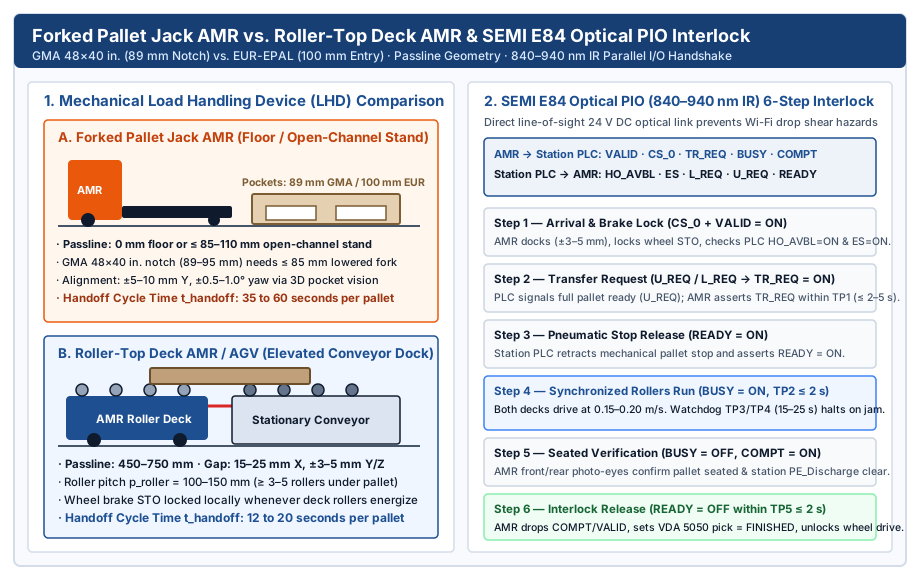
Because VDA 5050 runs over plant Wi-Fi (MQTT QoS 0), a 500 to 2,000 ms access-point roaming delay during a motorized roller transfer can leave one roller deck turning while the other halts, or allow traction wheels to move while a 1,200 kg pallet bridges the 15 to 25 mm gap. High-throughput packaging lines gate the physical transfer with a direct line-of-sight optical interface following the Hokuyo SEMI E84 parallel I/O (PIO) standard (840–940 nm infrared transceivers wired to 24 V DC PLC discrete I/O):
| Step | Active SEMI E84 Signals | Timeout Watchdog | Physical Machine & AMR Interlock Action |
|---|---|---|---|
| 1. Dock & Lock | AMR: CS_0 = ON, VALID = ON · PLC: HO_AVBL = ON, ES = ON |
Continuous link check | AMR reaches ±3–5 mm alignment, engages wheel brake STO lock, and establishes optical link with healthy station PLC |
| 2. Transfer Request | PLC: U_REQ = ON (or L_REQ) → AMR: TR_REQ = ON |
TP1 ≤ 2 to 5 s |
Palletizer discharge photo-eye confirms full pallet ready (U_REQ); AMR acknowledges transfer request |
| 3. Release Stop | PLC: READY = ON |
TP2 ≤ 2 s |
Palletizer PLC retracts pneumatic end-stop cylinder and locks upstream accumulation zone |
| 4. Rollers Run | AMR: BUSY = ON (both roller decks energized) |
TP3 / TP4 ≤ 15 to 25 s |
Stationary and AMR rollers drive synchronously at 0.15–0.20 m/s; if ES or optical link drops or timer expires, both halt immediately |
| 5. Seated Check | PLC: U_REQ = OFF → AMR: BUSY = OFF, COMPT = ON |
Debounce 0.3–0.5 s |
Station exit photo-eye clears and AMR front/rear presence sensors confirm pallet is fully seated inside chassis envelope |
| 6. Release & Depart | PLC: READY = OFF → AMR: TR_REQ = OFF, COMPT = OFF, VALID = OFF |
TP5 ≤ 2 s |
Handshake closes; AMR marks VDA 5050 pick action FINISHED, updates loads[] with pallet ID, and unlocks wheel drive |
Where optical PIO transceivers are not fitted and the handshake is coordinated over OPC UA + VDA 5050 (waitForTrigger / trigger), the AMR’s onboard safety PLC must still hard-interlock traction wheel STO whenever onboard deck rollers or fork lift hydraulics are energized, and verify zero overhang on the front load-presence photo-eye before releasing the wheel brakes. Keep the pallet unit identity and completion bits aligned with case packing and palletizing integration.
How to size pallet discharge accumulation and interlock timeouts
Takeaway: To prevent an end-of-line palletizer from entering PackML Held / Blocked while waiting for a mobile robot, the number of physical pallet accumulation zones downstream of the build bay must be at least ceil((t_dispatch_latency + t_handoff) / t_pitch).
Extending the package queue formula from conveyor accumulation time and buffer sizing (N = ceil(R × t / 60)) to whole pallets at the end of the line, define the palletizer’s finished-pallet pitch time (t_pitch, in seconds per pallet) from its production rate R_pal (pallets/hour):
t_pitch = 3,600 / R_pal
N_buffer_zones = ceil((t_dispatch_latency + t_handoff) / t_pitch)
Where t_dispatch_latency is the elapsed travel and traffic-clearance time from the moment the palletizer requests a pickup until the AMR reaches the docking threshold (seconds), and t_handoff is the complete docking, interlock, transfer, and departure clearance duration (12 to 20 s for a roller-top AMR; 35 to 60 s for a forked pallet jack AMR).
- Worked calculation — Scenario A (Roller-top AMR with Horizon pre-staging): A packaging line runs
24 cases/minat48 cases/pallet, producingR_pal = 30 pallets/hour(1 pallet every t_pitch = 120 s). By publishing a VDA 5050orderwhen the palletizer begins layer 5 of 6 so the AMR pre-stages at a waiting node (t_dispatch_latency = 15 safter final layer completion) and using a roller-top deck (t_handoff = 18 s), total discharge occupancy is15 + 18 = 33 s. Required downstream buffer zones:N_buffer_zones = ceil(33 / 120) =1 accumulation zone. - Worked calculation — Scenario B (Forked pallet jack AMR dispatched after pallet completion): On the same
t_pitch = 120 sline, if the fleet manager dispatches a forked pallet jack AMR only after the pallet is complete (t_dispatch_latency = 95 sfrom a remote staging lane) and the 90° turn plus fork insertion/withdrawal takest_handoff = 50 s, total occupancy is95 + 50 = 145 s. Because145 s > 120 s, a single discharge zone causes the palletizer to block for145 − 120 = 25 son every pallet (12.5 min/hour, or20.8%lost availability). Preventing blockage requiresN_buffer_zones = ceil(145 / 120) = 2downstream pallet accumulation zones (or triggering VDA 5050 pre-dispatch45 sbefore pallet completion). See line buffers and packaging handoffs for how upstream release and downstream space signals separate buffer occupancy from machine nameplate speed.
Where this integration boundary stops
Takeaway: Keep the VDA 5050 fleet message specification separate from the site’s ISO 3691-4:2023 safety risk assessment and the packaging PLC’s local interlock program.
VDA 5050 defines the MQTT and JSON message contract between a fleet controller and mobile robots; it does not calculate safety laser scanner field polygons, certify ISO 13849-1 PL d braking circuits, or replace the station PLC interlock program. Safety zone switching distances (S_stop), muting sensor placement around conveyor stands, and emergency stop integration must be validated on the physical installation under ISO 3691-4:2023 and ANSI/A3 R15.08-2 with the actual floor friction, maximum pallet mass, and braking deceleration taken from the robot manufacturer’s factsheet.
Reach the parent boundary note at AMR handoffs at a packaging line or browse all guides in Intralogistics.